
Owner's manual


ENGLISH
Chapter 2: Installaon
DVR User’s Manual
25
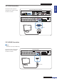
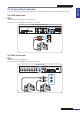
2.8.2 Direct BNC Connecon
Note:
Available in 16-channel DVRs only.
Connect the microphone(s) for channels 1 to 4 using direct BNC connecon as shown.
Microphone
CH1
CH9
CH2
CH10
CH3
CH11
CH4
CH12
CH5
CH13
CH6
CH14
CH7
CH15
CH8
CH16
1
3
2
AUDIO
IN
4
AUDIO OUT
MAIN
AUDIO OUT
SPOT
VIDEO OUT
MAIN
VIDEO OUT
SPOT
AUDIO IN (CH5-CH16)
HDMI VGA
DC 12V
LAN
G 12345678910 11
+
-
NO COM
G1615141312
RS-485 OUT
D
-
D
+
KB IN
ALARM
1
3
2
AUDIO
IN
4
BNC cable
16-Channel DVR
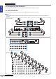
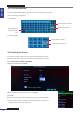
2.8.3 Parallel Connecon
Note:
Available in 16-channel DVRs only.
Use this connecon to connect microphones for channels 5 to 16.
CH1
CH9
CH2
CH10
CH3
CH11
CH4
CH12
CH5
CH13
CH6
CH14
CH7
CH15
CH8
CH16
1
3
2
AUDIO
IN
4
AUDIO OUT
MAIN
AUDIO OUT
SPOT
VIDEO OUT
MAIN
VIDEO OUT
SPOT
AUDIO IN (CH5-CH16)
HDMI VGA
DC 12V
LAN
G 12345678910 11
+
-
NO COM
G1615141312
RS-485 OUT
D
-
D
+
KB IN
ALARM
AUDIO IN (CH5-CH16)
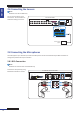
Microphone
Parallel-to-BNC
Adapter
16-Channel DVR
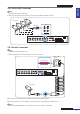
1 Connect the microphone(s) to the BNC end of the Parallel-to-BNC adapter.
2 Connect the other end of the adapter to the parallel port on the back of the DVR as shown.
Note:
The Parallel-to-BNC adapter is sold separately. Contact your dealer to purchase.