
Owner manual
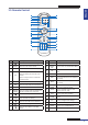

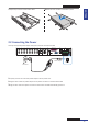


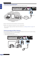


Table Of Contents
- About this Manual
- Chapter 1: Product Overview
- Chapter 2: Installation
- Chapter 3: Getting Started
- Chapter 4: Using the DVR
- Chapter 5: KGuard Web Client
- 5.1 Login
- 5.2 The Interface
- 5.3 Live Viewing
- 5.4 Searching and Playing Recorded Videos
- 5.5 Remote Settings
- 5.6 Local Settings
- Chapter 6: Using KView Series Software
- Chapter 7: Troubleshooting & FAQ
- Appendix: Specifications

ENGLISH
Chapter 2: Installaon
16
DVR User’s Manual
2.4.2 RS-485 Connecon
If you are using a PTZ speed dome, connect the camera cable to the video input of the DVR via RS-485 connector as
shown.
Speed dome
VGA
AUDIO IN (CH5-CH16)
HDMI
DC 12V
LAN
MAIN
SPOT
AUDIO OUTVIDEO OUT AUDIO IN
2
4
1
3
MAIN
SPOT
CH8
CH16
CH7
CH15
CH6
CH14
CH5
CH13
CH4
CH12
CH3
CH11
CH2
CH10
CH1
CH9
G 12345678910 11
+
-
NO COM G1615141312
RS-485 OUT IN
ALARM
G1 2345678910 11
+
-
NO COM G1615141312
RS-485 OUT IN
ALARM
2.5 Connecng the Alarm
You can connect one alarm device via RS-485 connecon as shown.
VGA
AUDIO IN (CH5-CH16)
HDMI
DC 12V
LAN
MAIN
SPOT
AUDIO OUTVIDEO OUT AUDIO IN
2
4
1
3
MAIN
SPOT
CH8
CH16
CH7
CH15
CH6
CH14
CH5
CH13
CH4
CH12
CH3
CH11
CH2
CH10
CH1
CH9
G 12345678910 11
+
-
NO COM G1615141312
RS-485 OUT IN
ALARM
G12345678910 11
+
-
NO COM G1615141312
RS-485 OUT IN
ALARM
Alarm output
2.6 Connecng the Sensors
You can connect sensors up to 16 channels. The connectors are labelled according to channels.
VGA
AUDIO IN (CH5-CH16)
HDMI
DC 12V
LAN
MAIN
SPOT
AUDIO OUTVIDEO OUT AUDIO IN
2
4
1
3
MAIN
SPOT
CH8
CH16
CH7
CH15
CH6
CH14
CH5
CH13
CH4
CH12
CH3
CH11
CH2
CH10
CH1
CH9
G 12345678910 11
+
-
NO COM G1615141312
RS-485 OUT IN
ALARM
G12345678910 11
+
-
NO COM G1615141312
RS-485 OUT IN
ALARM
Sensor device
(input)