
Installation Guide

CAUTION
WHEN INSTALLING KICHLER
®
LANDSCAPE LIGHTING
(LINE VOLTAGE OR LOW VOLTAGE), CARE SHOULD BE
TAKEN TO KEEP CLEAR OF POTENTIALLY COMBUSTI-
BLE MATERIALS. FIXTURES SHOULD NOT BE MOUNTED
ON OR ADJACENT TO COMBUSTIBLE MATERIALS.
WHEN MAINTAINING THE FIXTURES, BE SURE TO RE-
MOVE LEAVES, PINE NEEDLES, GRASS CLIPPINGS,
MULCH, OR ANY DEBRIS THAT HAS ACCUMULATED ON
THE LIGHT BULB, LENS, OR BODY OF THE FIXTURE.
ASSEMBLY AND INSTALLATION
• Installation should be done by a qualied electrician in accordance with
local, state and national electric codes.
• Excavation for conduit and conduit runs should be completed before proceeding.
• If installing xture in concrete using Kichler pour kit 15608AZ (sold separately)
follow dirctions included with pour kit and skip steps 3,5 and 6.
1) Turn off power.
2) Remove retaining ring, glass and yoke assembly.
3) At desired location, dig hole approximately 3” larger in diameter and depth
then well light.
4) Attach conduit to bottom of well light. To avoid water from entering well
light, thread sealant should be used. NOTE: Bottom of well light has two
holes for connection of conduit. Hole not being used should be plugged
using plug provided. Conduit connector may be torqued to a maximum
16 ft. lb (200 in. lb) for 12.7mm (1/2 in.) opening or 36 ft. lb (432 in. lb) for
19mm (3/4 in.) opening.
5) Fill bottom of hole with approximately 3” of pea gravel or equivalent granular
material. Top edge of well light should be at or slightly above nish grade.
Adjust by adding or removing material.
6) Back ll area between well light and hole with pea gravel or equivalent
granular material.
7) Completely seal conduit connections inside well light using provided gel
encapsulate.
8) Connect supply wires to ballast connections (connectors not provided).
Reference chart for correct connections and wire accordingly.
9) Adjust angle for bulb by loosening wing nuts inside yoke assembly and
adjust bottom end of yoke. Once at desired angle tighten wing nuts.
10) Slip yoke assembly into well light and secure in place with screws.
*NOTE: Reector must be used with ED17 lamp. When usING PAR 30/38
lamp, remove reector.
11) Insert recommended lamp. Lamp strike time may vary from instantaneous
to 5 minutes depending upon lamp/manufacturer used.
12) Insure that all gasket seating surfaces and screw holes are free and clear
of debris. If screw holes are not clear blow debris out or clear with #10-32
tap.
13) Slip glass with gasket into well light.
14) Slip screws previously removed in step 2 through holes in retaining ring.
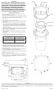
15) Align screws with holes in well light and tighten using an alternating torque
sequence at 20-30 inch-lbs. (SEE ILLUST. – Numbers indicate order in
which to tighten screws.)
WARRANTY
WE WARRANT THE LANDSCAPE PRODUCTS FEATURED IN OUR LANDSCAPE LIGHTING CATALOG (WITH THE EXCEPTION OF LIGHT BULBS) FOR FIVE
YEARS AGAINST DEFECTS IN MATERIALS AND WORKMANSHIP IF IT WAS PROPERLY INSTALLED AND FAILED UNDER NORMAL OPERATING CONDITIONS,
PROVIDED IT IS RETURNED TO THE POINT OF PURCHASE, WHERE IT WILL BE REPAIRED OR, AS IT MAY BE DETERMINED, TO REPLACE THE LANDSCAPE
PRODUCT OR PARTS USED ON THAT PRODUCT.
SCREW
RETAINING RING
GLASS
YOKE ASSEMBLY
1
8
4
5
3
7
2
6
Date Issued: 11/7/08 IS-15263-US
Connect Black or
Red Supply Wire to:
Connect
White Supply Wire to:
Black White
Insulated wire (other than green)
with copper conductor
Insulated wire (other than green)
with silver conductor
WELL LIGHT
REFLECTOR
*
SUPPLY
GREEN
WHITE
BLACK BLACK
GREEN
BLACK
SOCKET
WHITE
GREEN
WHITE
BLACK
BLACK
RED
YELLOW
YELLOW
BLACK
WHITE