
Instructions / Assembly

• Thispowersupplyisforusewithlandscapelightingsystemsonly.
• Donotsubmergetransformer.
• Thisdeviceisacceptedasacomponentofalandscapelightingsystem
wherethesuitabilityofthecombinationshallbedeterminedbyNational
ElectricCodeorlocalauthoritieshavingjurisdiction.
• WARNING: Riskofelectricshock,useonlywithlowvoltagelandscape
xturesandaccessories.DOnotusewithswimmingpoolorspalighting
xtures.
• Donotconnecttwoormorepowersuppliesinparallel.
• Suitableforindoororoutdooruse.
• Foruseindwellingsonlywithprovidedconduitadapterplate.
• NationalElectricalCoderequiresthatwiringwhereconcealedor
extendedthroughabuildingwallmustbeenclosedinconduit.
• Transformershouldbemountedclosetopowersource.Extensioncords
shouldnotbeusedwiththisunit.
• WARNING:(forPowerSupplyCordconnectedPOWERUNIT)
RISKOFELECTRICSHOCK.Installpowerunit5feet(1.5m)ormore
fromthepool,spa,orfountainwherethepowerunitisinstalled(a)
indoorwithin10feet(3.0m)ofapool,spa,orfountain,or(b)outdoor,
connectpowertounittoareceptacleprotectedbyaGFCI.
• Thisoutdoorpowerunitshallbeconnectedtoa115/120voltcovered
GFCIreceptaclemarked“WetLocation”whileinuse.
• Mounttherain-tighttransformeratleastonefootabovegroundlevelwith
thewireterminalsfacingdown.NOTE:Donotenergizetransformeruntil
installationofsystemiscomplete.
• Directburialratedwireistobeburiedaminimumof6”(152mm)beneath
thesurfaceoftheground.
NOTE:IfadditionalDirectBurialwireisneeded,contactyourlocal
Kichler
®
landscapedistributor.
• 8GAwirecanbepurchasedinlengthof250’(76M),15503-BK.
• 10GAwirecanbepurchasedinlengthof250’(76M),15504-BK.
•12GAwirecanbepurchasedinlengthsof100’(30M),15501-BK;250’
(76M),15502-BK;500’(152M),15505-BK;and1000’(304M),15506-BK.
• Finding Transformer Load:Lowvoltagesystemsrequiretheuseofa
transformertoreducestandard120-VOLTpowerfromyourhometo
12-VOLTS.Todeterminethetransformersizeyouwillneed,addupthe
wattagesofalllampsyouplantouse.Selectatransformerthatmatches
ascloselyaspossibletothetotallampwattage.Forexample,ifyou
have11xturesallratedat24.4watts,youwillneeda300watt
(VA)transformer(11x24.4=268.4watts).Generally,thetotallampload
shouldnotbelessthanone-thirdthetransformerswattagerating,nor
exceeditsmaximumwattagecapacity.Ifyourtotalwattageistoohigh,
eitherdividetheloadbetweentwotransformers,oruseamorepowerful
transformer.
ThisinstructionsheetcoverstheinstallationofthefollowingKichler
®
Transformers:15PL100AZT,15PL200AZT,15PL300AZT,15PL600AZT,
15PL900AZT.Readtheseinstructionscarefullybeforeinstallingthisunit.
1) Determinedesiredlocationformountingtransformer.NOTE:When
decidinglocationformountingconsiderationshouldbetakenforthe
requirementslistedabove.
2) Markpositionoftopportionofthekeyholeslotlocationattopof
transformerandtheslotlocatedatbottom.
3) Ifmountingtoasolidsurfacesuchaswood,siding,etc;
A)Drill1/8”diameterpilotholesatpositionsmarkedinStep2.
B)Drivescrewsapproximatelyhalfwayintoholes.
Ifmountingtodrywall:
A)Drill1/4”diameterholesatpositionsmarkedinStep2.
B)Pushplasticanchorsintoholesandtapuntilush.
C)Drivescrewsapproximatelyhalf-wayintoplasticanchors.
4) Sliplargeportionofkeyholeoverheadoftopscrewandallowtransformer
toslidedown,makingsurebottomslotisbehindheadofbottomscrew.
5) Tightenscrewsuntiltransformerissecure.
6) Split12/2.10/2,or8/2cableapproximately3”,andstrip1/2”insulation
offeachwire.12/2.10/2,and8/2cableistheheavyblackcablewhich
allKichler
®
12-voltlowvoltagelightingxtureswillbeconnected.
(Referenceabovefordescriptionandpartnumbers).
7) Onthebottomoftheterminalblockpushonebarewireintothehole
marked“COM”andtightenthecorrespondingscrewonterminalblock
faceuntilwireissecure.Seechartforterminalscrewtorquespecication.
NOTE:600Wand900Wtransformer(15PL600AZTand15PL900AZT)
ismanufacturedat300Wpercircuitwitheachterminalblockrepresenting
onecircuit.
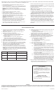
Seechartformaximumwiresizesandcounts.
CIRCUIT BREAKER
(SECONDARYSIDE-12VOLTSIDE)
•Circuitbreakerwilltripifthereisashortoriftotal
wattageinstalledexceedsratedwattagepercircuit.
•Toresetbreaker,ipswitchto‘OFF’thenbackto
‘ON’position.
•Iftheunitcyclesonandoffwithoutregardtothe
timersetting,itshouldbecheckedbyaqualied
serviceperson.
THERMAL PROTECTION
(PRIMARYSIDE-120VOLTSIDE)
•Thisunitisequippedwithathermalprotectorand
willshutoffifoverheated.
INSTALLATION INSTRUCTIONS
DateIssued:4/8/11 IS-15518-US
WARRANTY
We Warrant our transformers for ten years on aZt units and lifetime on stainless steel units against defects in material and Workmanship if it is prop-
erly installed and failed under normal operating conditions, provided it is returned to the point of purchase, Where it Will be repaired or, as it may be
determined, to replace the transformer.
8) Determinetheappropriatevoltagetap(holesmarked12V,13V14V,or5V)
forremainingbarewire.
• Foroptimumlightoutput,thevoltageatthelampsocketshould
rangebetween10.8and12volts.
Formoreinformationonvoltagedrop,consulttheKichlerLandscape
LightingCatalogorcontactyourlocalKichlerdistributor.
9) Pushremainingbarewireintotheappropriateholeonbottomof
terminalblockandtightenthecorrespondingscrewonterminalblock
faceuntilwireissecure.Againrefertotorquespecicationsinchart.
10)Aboveterminalblocksisareceptacleandashortpowercord.
• Ifusingplug-intimer(15556WH/15557BK):
A) Plugtimerintoreceptacle.
B) Plugshortpowercordintotimer
` C) Settimerfollowinginstructionsprovidedwithtimer.
• Ifnotusingplug-intimer:
A) Plugshortpowercordintoreceptacle.
11)OptionalPhotocontrolInstallations:
A) MakesurepowerisoffandtransformerisNOTpluggedinto
anelectricaloutlet.NOTE:Nospliceisrequired,transformeris
equippedwithjumperconnector.
B) Openfrontcoverofthetransformercasebyliftingthecover
up.Locateanddisconnectthewhitejumperconnectorinside
thehousing.*Savethejumperconnectorwiththeseinstructions
forpossiblefutureuse.
C) Removeone(1)ofthe7/8”diameterknockoutsonthesideof
thetransformerandpushthephotocontrolwhiteconnector
throughtheknockouthole.Insidethehousing,slidethespacer
andstarnutoverthewhiteconnectorandthreaditontothe
photocontrolandtighten.
D) Plugphotocontrolwhiteconnectorintothehousingconnector.
Insurethatthesidelatchlockstheconnectors.
E) Locatetransformerandpositionphotocontrolsothatnolight
willshineonthecell.Itwillcausethephotocontroltocycleon
andoff.*Intheunlikelyeventthatthephotocontrolshouldfail,
thelightingxtureswillremainon,eveninthedaytime.Ifthis
shouldhappen,followtheseinstructionsandremovethedefective
photocontrolandplacethejumperconnectorinitsplace.
12)Plugpowersupplycordintostandard115/120voltreceptacle.NOTE:
Thepowersupplycordmustbepluggedintoaweathertightreceptacle
equippedwithaGroundFaultInterrupter(GFCI).
Wire Sizes
#12
#10
#8
Max. no. of conductors
8
4
1
Tightening Torque
3.6-4.0N-m(32-35lb-in)
3.6-4.0N-m(32-35lb-in)
4.1-4.5N-m(36-40lb-in)