1 1. SAFETY RULES 1. To reduce the risk of electric shock, insure electricity has been turned off at the circuit breaker or fuse box before beginning. 2. All wiring must be in accordance with the National Electrical Code and local electrical codes. Electrical installation should be performed by a qualified licensed electrician. 3. WARNING: Suitable for use with solidstate speed controls. 4.
Canfield 2. TOOLS AND MATERIALS REQUIRED Philips screw driver Blade screw driver 11 mm wrench Step ladder Wire cutters 3. PACKAGE CONTENTS Unpack your fan and check the contents. You should have the following items: a. b. c. d. e. f. g. h. i.
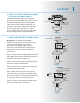
3 4. MOUNTING OPTIONS If there isn't an existing UL (CUL for Canadian Installation) listed mounting box, then read the following instructions. Disconnect the power by removing fuses or turning off circuit breakers Outlet box Fig. 1 Secure the outlet box directly to the building structure. Use appropriate fasteners and building materials. The outlet box and its support must be able to fully support the moving weight of the fan (at least 50 lbs). Do not use plastic outlet boxes.
Canfield TM 5. HANGING THE FAN REMEMBER to turn off the power. Follow the steps below to hang your fan properly: Hanger bracket Ceiling canopy Step 1. Remove the decorative canopy bottom cover from the canopy by turning the cover counter clockwise. (Fig. 5) Canopy cover Step 2. Remove the hanger bracket from the canopy by loosening the two screws on the bottom of the hanging bracket. Turn the canopy counterclockwise and remove. (Fig, 5) Step 3.
5 Downrod Canopy Canopy cover Coupling cover Set screws Lock pin Hitch pin Fig. 9 Registration slot Fig. 10 Step 7. Slip coupling cover, canopy cover and canopy onto downrod. Carefully reinstall hanger ball onto rod being sure that cross pin is in correct position, the set screw on hanger ball is tight and wires are not twisted. (Fig. 9) Step 8. Now lift the motor assembly into position and place the hanger ball into the hanger bracket.
Canfield TM 6. INSTALLATION OF SAFETY SUPPORT (for Canadian Installation ONLY) An additional safety support is provided to prevent the fan from falling fan). Place the end of cable through the loop of ceiling support cable. Pull as much cable through loop as possible. Feed end of cable into clamp hole and fi rmly tighten screw (Fig. 11). Cut off excess safety cable. Secure the safety cable to the ceiling joist with screw and washer.
7 GREEN GROUND WIRING BOX GROUND TO MOUNTING BRACKET OR DOWNROD FAN WH BLK FAN BLUE LIGHT WH BLK POWER LINES 120V BLUE WH BLK WH LIGHT Figures 13 and 14 illustrate the wiring connections for optional wall control (The wire color out of wall control may vary, see wall control's installation manual for correct wire connections.) WARNING: TO REDUCE THE RISK OF FIRE, ELECTRIC SHOCK, OR OTHER PERSONAL INJURY. MOUNT FAN ONLY ON AN OUTLET BOX OR SUPPORTING SYSTEM MARKED ACCEPTABLE FOR FAN SUPPORT.
Canfield TM 8 9. ATTACHING THE FAN BLADES Caution: Remove 5 rubber packing mounts and discard before installation. Step 1 Attach the blade to the blade bracket using the screws, washers and fiber washers as shown in Figure 16. Start screw into bracket. Repeat for the two remaining screws. Screws Step 2 Make sure the blade is straight and tighten each screw. Step 3 Fasten blade assembly to motor using "Pre-Installed" mounting screws in the blade bracket.
9 11. INSTALLING THE SWITCH HOUSING NOTE: Before starting installation, disconnect the power by turning off the circuit breaker or removing the fuse at fuse box. Turning power off using the fan switch is not sufficient to prevent electric shock. 1. While holding the switch housing under your fan, snap together the wire connection plugs . 2. Carefully push all wires back into the switch housing, then install the switch housing onto the mounting plate with 3 screws provided. Be sure to tighten all screws.
Canfield 12. OPERATING INSTRUCTIONS Turn on the power and check the operation of your fan. The pull chain controls the fan speed as follows: 1. 3-speed pull chain- it controls the fan speed as follows: 1 pull- High, 2 pulls- Medium, 3 pulls- Low, and 4 pulls- Off. Speed settings for warm or cool weather depend on factors such as the room size, ceiling height, number of fans, and so on. The slide switch controls directions: forward (switch left) or reverse (switch right). Fig.
11 13. TROUBLESHOOTING Problem Solution Fan will not start. 1. Check circuit fuses or breakers. 2. Check line wire connections to the fan and switch wire connections in the switch housing. CAUTION: Make sure main power is off. Fan sounds noisy. 1. Make sure all motor housing screws are snug. 2. Make sure the screws that attach the fan blade bracket to the motor hub is tight. 3. Make sure wire nut connections are not rubbing against each other or the interior wall of the switch housing.