1 1. SAFETY RULES 1. To reduce the risk of electric shock, insure electricity has been turned off at the circuit breaker or fuse box before beginning. 2. All wiring must be in accordance with the National Electrical Code and local electrical codes. Electrical installation should be performed by a qualified licensed electrician. 3. WARNING: Suitable for use with solidstate speed controls. 4.
Hendrick TM 2 2. TOOLS AND MATERIALS REQUIRED Philips screw driver Blade screw driver 11 mm wrench Step ladder Wire cutters 3. PACKAGE CONTENTS Unpack your fan and check the contents. You should have the following items: a. b. c. d. e. f. g. h. i. j. k. l.
3 4. MOUNTING OPTIONS If there isn't an existing UL (CUL for Canadian Installation) listed mounting box, then read the following instructions. Disconnect the power by removing fuses or turning off circuit breakers Outlet box Fig. 1 Secure the outlet box directly to the building structure. Use appropriate fasteners and building materials. The outlet box and its support must be able to fully support the moving weight of the fan (at least 50 lbs). Do not use plastic outlet boxes.
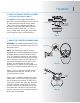
Hendrick TM 5. HANGING THE FAN Hanger bracket REMEMBER to turn off the power. Follow the steps below to hang your fan properly: Ceiling canopy Step 1. Remove the decorative canopy bottom cover from the canopy by turning the cover counter clockwise. (Fig. 5) Step 2. Remove the hanger bracket from the canopy by loosening the two screws on the bottom of the hanging bracket. Turn the canopy counterclockwise and remove. (Fig, 5) Step 3.
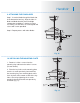
5 Downrod Canopy Canopy cover Set screws Coupling cover Lock pin Hitch pin Fig. 9 Registration slot Fig. 10 Step 7. Slip the coupling cover, canopy cover and canopy onto downrod. Carefully reinstall hanger ball onto rod being sure that cross pin is in correct position, the set screw on hanger ball is tight and wires are not twisted. (Fig. 9) Step 8. Now lift the motor assembly into position and place the hanger ball into the hanger bracket.
Hendrick TM 6. INSTALLATION OF SAFETY SUPPORT (for Canadian Installation ONLY) An additional safety support is provided to prevent the fan from falling fan). Place the end of cable through the loop of ceiling support cable. Pull as much cable through loop as possible. Feed end of cable into clamp hole and fi rmly tighten screw (Fig. 11). Cut off excess safety cable. Secure the safety cable to the ceiling joist with screw and washer.
7 Outlet box White (neutral) Black (hot) Green or bare copper (ground) Black ("AC IN L") White ("AC IN N") Receiver Step 3. (Fig. 14) Receiver to House Supply Wires Electrical Connections: Connect the black (hot) wire from the ceiling to the black wire marked "AC in L" from the receiver. Connect the white(neutral) wire from the ceiling to the white wire marked "AC in N" from the Receiver. Secure the wire connections with the plastic wire nuts provided.
Hendrick TM 9. ATTACHING THE FAN BLADES Step 1. Insert the blade through the blade slot in the decorative housing. Align the holes in blade and blade bracket, place the blade support plate on blade as showing in Figure 16, making sure the holes are also aligned and secure with screws provided. Step 2. Repeat process with other blades. Slot Blade Blade support plates Screws Fig. 16 10. INSTALLING THE MOUNTING PLATE 1. Remove 1 of the 3 screws from the mounting ring and loosen the other 2 screws.
9 11. INSTALLING THE LIGHT KIT NOTE: Before starting installation, disconnect the power by turning off the circuit breaker or removing the fuse at fuse box. Step 1. Loosen the 3 screws from the bottom of the motor housing. Step 2. Raise and hold the light kit close to the motor housing. Connect the white wire connectors from the light kit and fan. Follow the same procedure with the black wire connectors. (Fig. 18) Connection plugs Motor housing Light kit Screws Step 3.
Hendrick 13. INSTALLING THE BATTERY IInstall 2, 3 volt (#2032) batteries included with the CoolTouchTM Control System. (Fig. 20) Note: To prevent damage to the transmitter, remove these batteries if not used for long periods of time (months). Fig. 20 14. OPERATING INSTRUCTIONS Restore power to ceiling fan and test for proper operation. A. , , and buttons: These three buttons are used to set the fan speed as follows: = high speed = medium speed = low speed B. button: This button turns the fan off. C.
11 Speed settings for warm or cool weather depend on factors such as the room size. Ceiling height, number of fans and so on. NOTE: To operate the reverse function on this fan, press the reverse button while the fan is running. Fig. 22 Warm weather-(Forward) A downward airflow creates a cooling effect as shown in Fig. 22. This allows you to set your air conditioner on a warmer setting without affecting your comfort.
Hendrick 15. INSTALLING THE COOLTOUCHTM CONTROL SYSTEM WALL PLATE TM Ou t l et b o x Sw i t c h To install the CoolTouchTM control system wall plate, you can select the following locations to fulfill your wall plate installation: Wal l p l at e 1. Using the existing wall outlet box: Step 1. Remove the existing wall plate and the old switch from the wall outlet box. Wire nut the BLACK leads (hot) together and push back inside the outlet box. (Fig. 24) Step 2.
13 17. TROUBLESHOOTING Problem Solution Fan will not start. 1. Check circuit fuses or breakers. 2. Check line wire connections to the fan and switch wire connections in the switch housing. CAUTION: Make sure main power is off. 3. Check to make sure the dip switches from the transmitter and receiver are set to the same frequency. 4. Check to make sure the batteries are installed properly, (Positive + side facing out) 5. Check to make sure the batteries are not dead. Fan sounds noisy. 1.