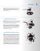
Shuriken TM 300209 A Kichler Decor ceiling fan ® ™ Includes our new CoolTouchTM Control System Looks permanent, but goes wherever you go! U.S. Patent Pending Kichler® Lighting 7711 East Pleasant Valley Road P.O. Box 318010 Cleveland, Ohio 44131-8010 Instruction Manual Customer Service 866.558.
1 1. SAFETY RULES 1. To reduce the risk of electric shock, insure electricity has been turned off at the circuit breaker or fuse box before beginning. 2. All wiring must be in accordance with the National Electrical Code and local electrical codes. Electrical installation should be performed by a qualified licensed electrician. 3. WARNING: Suitable for use with solidstate speed controls. 4.
Shuriken TM 2 2. TOOLS AND MATERIALS REQUIRED Philips screw driver Blade screw driver 11 mm wrench Step ladder Wire cutters 3. PACKAGE CONTENTS Unpack your fan and check the contents . You should have the following items: A. Mounting bracket B. Ball / downrod assembly (1) C. Canopy D. Canopy Hole Cover E. Coupling cover F. Motor Body G. Fan Blades (4) H. Switch Housing Assembly (1) I. Light Kit J. Glass Shade K. Cool TouchTM Control System L.
3 4. MOUNTING OPTIONS If there isn't an existing ETL listed mounting box, then read the following instructions. Disconnect the power by removing fuses or turning off circuit breakers. Outlet box Fig. 1 Secure the outlet box directly to the building structure. Use appropriate fasteners and building materials. The outlet box and its support must be able to fully support the moving weight of the fan (at least 50 lbs). Do not use plastic outlet boxes.
Shuriken TM 4 5. HANGING THE FAN ETL Listed Outlet Box REMEMBER to turn off the power before you begin installation. This is necessary for your safety and also the proper programming of the control system. Ceiling Mounting Bracket Flat Washer Screw To properly install your ceiling fan, follow the steps below. Step 1.
5 Registration Slot Check Tab Step 5. Now lift the motor body into position and place the hanger ball into the hanger bracket. Rotate until the "Check Tab" has dropped into the "Registration Slot " and seats firmly. ( Fig. 9) The entire motor body should not rotate is this is done correctly. WARNING: Failure to properly seat the "Check Tab" can damage the ceiling fan during operation. Fig. 9 6 .
Shuriken 7. MAKE THE ELECTRIC CONNECTIONS TM 6 Battery Compartment WARNING: To avoid possible electrical shock, be sure you have turned off the power at the main circuit panel before wiring. Follow the steps below to connect the fan to your household wiring. Use the wire connecting nuts supplied with your fan. Secure the connector with electrical tape. Make sure there are no loose wire stands or connections. ON Code Switch Fig.
7 Step 3. Remote Receiver to Outlet Box Electrical Connections: Connect the BLACK (hot) wire from the ceiling to the BLACK wire marked “AC in L” from the receiver . Connect the WHITE ( neutral ) wire from the ceiling to the WHITE wire marked “ AC in N” from the Receiver . Secure the wire connections with the plastic wire nuts provided . ( Fig. 14) Step 4.
Shuriken Step 3. Securely attach and tighten the canopy hole cover over the shoulder screws in the mounting bracket utilizing the keyslot twist-lock feature. (Fig. 17) TM Shoulder Screw Canopy Hole Cover Fig. 17 9. ATTACHING THE FAN BLADES NOTE: Before continuing , make sure the power is disconnected by turning off the circuit breaker of removing the fuse at the circuit box. Step 1. Align the middle hole of one blade with the red dot label on the flywheel of motor body.
9 11. INSTALLING THE LIGHT KIT NOTE: Before continuing installation, confirm that the power is still turned off at the main circuit breaker or by removing the correct fuse. Turning the power off using a wall switch is not sufficient to prevent electrical stock. Step1. Remove one of the three screws preinstalled on the switch housing and loosen the other two (do not remove). Save it for reuse on step 3. (Fig. 20) Switch housing Step 2.
Shuriken 13. INSTALLING THE COOLTOUCH TM CONTROL SYSTEM WALL PLATE TM 10 Outlet Box All wiring must be in accordance with the National Electrical Code and local electrical codes.Electrical installation should be performed by a qualified licensed electrician. Switch Wall Plate Select a location to install your CoolTouchTM Control System Transmitter. You can replace an existing wall switch, or install the transmitter on ANY flat surface.
11 14. INSTALLING THE TRANSMITTER Step 1. To place the transmitter in the wall plate , put the bottom end in first and then press the top into the wall plate. The transmitter is now held in the wall plate and will function from here . ( Fig. 24) Step 2. To remove the transmitter from the wall plate. Push the release button and the transmitter will fall into your hand. Fig. 24 15. CONTROL SYSTEM SET-UP NOTE: Make sure the power is completely disconnected before you begin this procedure.
Shuriken 16. OPERATING INSTRUCTIONS: Speed Buttons Restore power to ceiling fan and test for proper operation. Figure 27 1.Buttons , , : These three buttons are used to set the fan speed as follows: TM Forward/Reverse Button = Low Speed = Medium Speed = High Speed Fig. 27 2. The " " button: controls fan direction, forward or reverse Speed setting for warm or cool weather depend on factor such as th room size. Ceiling height, number of fans and so on.
13 17. TROUBLESHOOTING Problem Solution Fan will not start. 1. Check circuit fuses or breakers. 2. Check all electrical connections to insure proper contact. CAUTION: Make sure the main power is OFF when checking any electrical connection. 3. Make sure the transmitter batteries are installed properly. Positive (+) side facing out. 4. Insure the batteries have a good charge. Fan sounds noisy. 1. Make sure all motor housing screws are snug. 2.