
Installation Sheet

WARNING:
• This fixture is intended for installation in accordance with the
National Electric Code (NEC) and all local code specifications.
• Supply wires are not intended for use through or concealed
behind walls, floors, or ceilings.
• The LED light output is strong enough to injure human eyes.
Precautions must be taken to prevent looking directly at LED’s
with unaided eyes for more than a few seconds.
DIMMING: This LED fixture is compatible with electronic low
voltage dimmers only.
1) Read and understand all instructions and illustrations completely
before proceeding with assembly and installation of fixture.
2) If you have any doubts about how to install this fixture, or if
the fixture fails to operate completely, please contact a
qualified electrician.
3) All parts must be used as indicated in the instructions. Do not
substitute any parts, leave parts out, or use any parts that are
worn or broken. Failure to obey this instruction could invalidate
the UL listing, C.S.A. certification, and/or ETL listing of this fixture.
4) Fixture is to be connected to a single branch circuit.
1) TURN OFF POWER.
IMPORTANT: Before you start, NEVER attempt any work
without shutting off the electricity until the work is done.
a) Go to the main fuse, or circuit breaker, box in your home.
Place the main power switch in the “OFF” position.
b) Unscrew the fuse(s), or switch “OFF” the circuit breaker
switch(s), that control the power to the fixture or room that
you are working on.
c) Place the wall switch in the “OFF” position. If the fixture to
be replaced has a switch or pull chain, place those in the
“OFF” position.
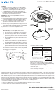
2) Grounding instructions: (See Illus. A or B).
A) On fixtures where mounting strap is provided with a hole
and two raise dimples. Wrap ground wire from outlet box
around green ground screw, and thread into hole.
B) On fixtures where a cupped washer is provided. Put ground
wire from outlet box under cupped washer and green
ground screw and thread screw into hole in mounting strap.
If fixture is provided with ground wire. Connect fixture ground
wire to outlet box ground wire with wire connector, (not provided)
after following the above steps. Never connect ground wire to
black or white power supply wires.
GREEN GROUND
SCREW
CUPPED
WASHER
A
B
OUTLET BOX
GROUND
FIXTURE
GROUND
DIMPLES
WIRE CONNECTOR
(NOT PROVIDED)
OUTLET BOX
GROUND
GREEN GROUND
SCREW
FIXTURE
GROUND
Connect Black or
Red Supply Wire to:
Connect
White Supply Wire to:
Black White
*Parallel cord (round & smooth) *Parallel cord (square & ridged)
Clear, Brown, Gold or Black
without tracer
Clear, Brown, Gold or Black
with tracer
Insulated wire (other than green)
with copper conductor
Insulated wire (other than green)
with silver conductor
*Note: When parallel wires (SPT I & SPT II)
are used. The neutral wire is square shaped
or ridged and the other wire will be round in
shape or smooth (see illus.)
Neutral Wire
Date Issued: 8/28/15 IS-43846LED-US
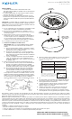
LENS COVER
PROTECCIÓN
DEL LENTE
FIXTURE
ARTEFACTO
We’re here to help 866-558-5706
Hrs: M-F 9am to 5pm EST
SCREW
TORNILLO
3) Make wire connections. Reference chart below for correct
connections and wire accordingly.
4) Mounting surface should be clean, dry, flat and 1/4” larger
than the fixture housing surface.
5) Twist lens cover counter-clockwise to remove from fixture.
6) Place fixture over outlet box, carefully passing fixture mounting
screws through clearance holes in canopy.
7) Any gaps in the mounting surface exceeding 3/16” should be
corrected as required.
8) Replace the lens cover back on the disk light by lining up tabs
on lens and turning to lock in place.
SEE OTHER SIDE FOR SPANISH TRANSLATIONS.
VEA EL OTRO LADO DE TRADUCCIONES AL ESPAÑOL.
This device complies with part 15 of the FCC Rules. Operation is subject to the following two conditions: (1) This device may not cause
harmful interference, and (2) this device must accept any interference received, including interference that may cause undesired operation.
Note: This equipment has been tested and found to comply with the limits for a Class B digital device, pursuant to part 15 of the FCC Rules.
These limits are designed to provide reasonable protection against harmful interference in a residential installation. This equipment gener-
ates, uses and can radiate radio frequency energy and, if not installed and used in accordance with the instructions, may cause harmful
interference to radio communications. However, there is no guarantee that interference will not occur in a particular installation. If this equip-
ment does cause harmful interference to radio or television reception, which can be determined by turning the equipment off and on, the
user is encouraged to try to correct the interference by one or more of the following measures:
• Reorient or relocate the receiving antenna.
• Increase the separation between the equipment and receiver.
• Connect the equipment into an outlet on a circuit different from that to which the receiver is connected.
• Consult the dealer or an experienced radio/TV technician for help.