
Instructions / Assembly


REV 18-JAN-2021
IS-52174-US
We’re here to help 866-558-5706
Hrs: M-F 9am to 5pm EST
MOUNTING WITHOUT CORD:
1) Find the appropriate threaded holes on mounng strap[A] that align
with hole distance in upper canopy[G]. Insert mounng screws[B]
into threaded holes.
2) Aach mounng strap to outlet box[C] using the strap mounng
screws[D]. The mounng strap can be adjusted to suit posion of
xture.
3) Remove the crimp wire nuts from the black and white wires inside
upper canopy[G], then slide the strain relief[E] o the cord.
4) Pull cord[K] out of xture from lower canopy[O].
5) Slide strain relief[E] inside lower canopy o cord.
6) Loosen screw in strain relief[Q] aached to lower canopy[O] and
pull cord out of xture completely.
7) Remove strain relief[Q] aached to lower canopy by unscrewing
hexnut inside lower canopy from threads (remove lock washer as
well).
8) Insert cap[R] into hole in boom of lower canopy[O].
9) Carefully push upper canopy[G] to wall over the mounng screws
protruding from the mounng strap. Secure into place using the two
lockwashers[H] and two ball knobs[I].
10) Once xture is hanging on the wall, mark the locaon of the lower
canopy[O] by tracing lightly around its outer edge.
11) Unscrew lockwashers and ball knobs, and remove xture from wall.
Locate the center of the lower canopy circle traced on the wall.
12) Using lower mounng bracket[P] as a guide, mark the two (2) hole
locaons for the drywall anchors on the wall. The mounng bracket
should be centered on the traced circle, and posioned horizontally
with the long at surface against the wall.
13) Drill the holes and insert two (2) plasc drywall anchors[N].
14) Aach the lower mounng bracket[P] to the wall using two (2)
bracket mounng screws[M].
15) Grounding instrucons: (See Illus. a or b).
a) On xtures where mounng strap is provided with a hole and
two raised dimples, wrap ground wire from outlet box around
green ground screw, and thread into hole.
b) On xtures where a cupped washer is provided,aach ground
wire from outlet box under cupped washer and green ground
screw, then thread into mounng strap.
If xture is provided with ground wire, connect xture ground wire
to outlet box ground wire with wire connector aer following the
above steps. Never connect ground wire to black or white power
supply wires.
16) Make wire connecon. Reference chart below for correct
connecons and wire accordingly.
Connect Black or Red
Supply Wire to:
Connect White Supply Wire
to:
Black White
*Parallel cord (round &
smooth)
*Parallel cord (square &
ridged)
Clear, Brown, Gold or Black
without Tracer
Clear, Brown, Gold or Black
with Tracer
Insulated wire (other
than green) with copper
conductor
Insulated wire (other than
green) with silver conductor
*Note: When parallel wire (SPT 1 &
SPT 2) are used. The neutral wire
is square shaped or ridged and the
other wire will be round in shape or
smooth
(see illus.) Neutral Wire
17) Carefully push upper canopy[G] to wall over the mounng screws
protruding from the mounng strap. Make sure lower canopy[O]
passes over lower mounng bracket[P] and that holes on the sides
of the lower canopy are aligned with holes on the sides of lower
mounng bracket aached to wall.
NOTE: Make sure all wires are inside upper canopy and do not get
pinched between wall and upper canopy of xture.
18) Secure upper canopy into place using the two lockwashers[H] and
two ball knobs[I].
19) Secure lower canopy by screwing countersunk mounng screws[F]
into aligned holes.
20) Insert recommended bulbs (not supplied).
21) Turn on the light by using the turn switch[J] on the shade just below
the swivel.
GREEN GROUND
SCREW
CUPPED
WASHER
OUTLET BOX
GROUND
FIXTURE
GROUND
DIMPLES
WIRE CONNECTOR
OUTLET BOX
GROUND
GREEN GROUND
SCREW
FIXTURE
GROUND
a
b
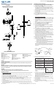
Fixture Diagram
Parts List
Cauons
CAUTION – RISK OF SHOCK –
Disconnect Power at the main circuit breaker panel or main fusebox before starng and during
the installaon.
WARNING:
This xture is intended for installaon in accordance with the Naonal Electrical Code (NEC) and all
local code specicaons. If you are not familiar with code requirements, installaon by a cered
electrician is recommended.
CLEANING:
• Always be certain that electric current is turned o before cleaning.
• Only a so damp cloth should be used. Harsh cleaning products may damage the nish.
Installaon Instrucons
[A] Mounting Strap
[B] Mounting Screws
[C] Outlet Box
[D] Strap Mounting Screws
[E] Strain Relief (Inside Canopy,
on Cord)
[F] Countersunk Mounting
Screws
[G] Upper Canopy
[H] Lock Washers
[I] Ball Knobs
[J] Turn Switch
[K] Cord
[L] Upper Mounting Bracket
[M] Bracket Mounting Screws
[N] Drywall Anchors
[O] Lower Canopy
[P] Lower Mounting Bracket
[Q] Strain Relief (Attached to
Lower Canopy)
[R] Cap
[S] Plug
Installaon Instrucons (connued)
For warranty informaon please visit: kichler.com/warranty
TOP VIEW:
UPPER MOUNTING BRACKET
(FOR MOUNTING WITH CORD)
MOUNTING WITH CORD:
1) Find a suitable locaon on the wall to mount your xture. Locaon should be within 7 feet of an electrical
outlet.
2) Using upper mounng bracket[L] as a guide, mark the two (2) hole locaons for the drywall anchors. Drill the
holes and insert two (2) plasc drywall anchors[N].
3) Aach the upper mounng bracket[L] to the wall using two (2) bracket mounng screws[M].
4) Carefully push upper canopy[G] to wall over the mounng screws[B] protruding from the upper mounng
bracket. Secure into place using the two lockwashers[H] and two ball knobs[I].
5) Once xture is hanging on the wall, mark the locaon of the lower canopy[O] by tracing lightly around its
outer edge.
6) Unscrew lockwashers and ball knobs, and remove xture from wall. Locate the center of the lower canopy
circle traced on the wall.
7) Using lower mounng bracket[P] as a guide, mark the two (2) hole locaons for the drywall anchors on the
wall. The mounng bracket should be centered on the traced circle and posioned horizontally, with the long
at surface against the wall.
TOP VIEW:
LOWER MOUNTING BRACKET
G
H
I
A
D
C
B
E
L
M
B
N
J
K
N
M
F
O
P
P
N
S
M
F
E
Q
R
8) Drill the holes and insert two (2) plasc drywall anchors[N].
9) Aach the lower mounng bracket[P] to the wall using two (2)
bracket mounng screws[M].
10) Carefully push upper canopy[G] to wall, over the mounng screws
protruding from the upper mounng bracket. Make sure lower
canopy[O] passes over lower mounng bracket[P] and that holes in
the sides of the lower canopy are aligned with holes on the sides of
lower mounng bracket aached to wall.
11) Secure upper canopy into place using the two lockwashers[H] and
two ball knobs[I].
12) Secure lower canopy by screwing countersunk mounng screws[F]
into aligned holes.
13) Insert recommended bulbs (not supplied).
14) Insert plug[S] into 120-volt electrical outlet.
15) Turn on the light by using the turn switch[J] on the shade just below
the swivel.