
Owner's Manual


2
PX.2-SERIES AMPLIFIERS
OWNER’S MANUAL
INSTALLATION
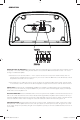
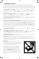
Mounting: Choose a structurally sound location to mount your KICKER amplifi er. Make sure there are no items
behind the area where the screws will be driven. Choose a location that allows at least 4” (10cm) of open
ventilation for the amplifi er. Drill four holes using a 7/64” (3mm) bit and use the supplied #8 screws to mount the
amplifi er.
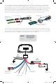
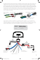
Wiring: Disconnect the vehicle’s battery to avoid an electrical short. Then, connect the PX harness to the
amplifi er. Connect the ground wire to a paint-and-corrosion-free, solid, metal area of the vehicle’s chassis,
making it no longer than 24” (60cm). Adding an additional ground wire of this same gauge (or larger) between the
battery’s negative post and the vehicle chassis is recommended.
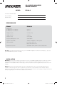
PERFORMANCE
Authorized KICKER Dealer:
Purchase Date:
Serial Number:
Model: PX100.2
RMS Power
@ 2 stereo, 1% THD+N
@ 4 stereo, 1% THD+N
50W x 2
25W x 2
Length, in. [cm] 6-5/16” [17.6]
Height, in. [mm] 2” [50.6]
Width, in. [mm] 3-1/2” [88.2]
Frequency Response ± 1dB 20Hz–20KHz
Signal-to-noise Ratio >85dB, A-weighted, re: rated power
Input Sensitivity Low Level: 125mV–5V
High Level: 250mV–10V
Electronic Crossover Selectable 100Hz, 250Hz or OFF; 24dB/octave
Pro Tip: To get the best performance from your new KICKER Amplifi er and extend the warranty by 1 year, use
genuine KICKER accessories and wiring.
MODEL: PX100.2
2012 PX 100.2 Rev F.indd 22012 PX 100.2 Rev F.indd 2 11/29/2011 2:45:41 PM11/29/2011 2:45:41 PM