CX AMPLIFIERS Owner’s Manual CXA660.5 Manual del Propietario | Español AMPLIFICADOR DEL LA SERIE CX.5 Benutzerhandbuch | Deutsch VERSTÄRKER DER CX.5-SERIE Manuel d’utilisation | Française AMPLIFICATEUR DE SÉRIE CX.
(fKICKER. MODEL: CX.5-SERIES AMPLIFIERS OWNER’S MANUAL CXA660.5 Authorized KICKER Dealer: Purchase Date: Serial Number: WARNING: KICKER products are capable of producing sound levels that can permanently damage your hearing! Turning up a system to a level that has audible distortion is more damaging to your ears than listening to an undistorted system at the same volume level. The threshold of pain is always an indicator that the sound level is too loud and may permanently damage your hearing.
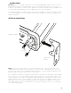
INSTALLATION Mounting: Choose a structurally sound location to mount your KICKER amplifier. Make sure there are no items behind the area where the screws will be driven. Choose a location that allows at least 4” (10cm) of open ventilation for the amplifier. If possible, mount the amplifier in the climate-controlled passenger compartment. Drill four holes using a 7/64” (3mm) bit and use the supplied #8 screws to mount the amplifier. The KICKER CX Amplifiers are capable of space-saving vertical mounting. Use a 2.
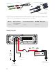
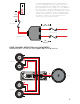
to amplifier core conductor source unit high-level speaker outputs KICKER KISL (optional) OR + – to amplifier shield from source unit highlevel speaker outputs Install a fuse within 18” (45cm) of the battery and in-line with the power cable connected to your amplifier. If you ever need to remove the amplifier from the vehicle after it has been installed, the ground wire should be the last wire disconnected from the amplifier--just the opposite as when you installed it.
For multiple amplifier installations where distribution blocks are used, each amplifier should have its proper-rated fuse, or breaker, installed between the amplifier and the distribution block within eighteen inches of the block, or on the distribution block if it provides for fusing.
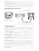
OPERATION FADER AMP1 AMP2 SUB IAMP1- IAMP2- 0••~•1: 0 _._ OFF X-OVER FREQ ~ ON INPUT SUB INPUT O0 LEVEL .A. LO !:iff/f X-OVER FREQ . PRT @ PWR l'SUB---, X-OVER BASS FREQ BOOST GAIN 50-200Hz 0 0- 6 (dB) • • • R:!fIE audio inputs Automatic Turn-On Selection: The CX series offers two different automatic turn-on modes; +12V and DC Offset.
Crossover Control: The variable crossovers on the side panel of the amplifier allow you to adjust the crossover frequency from 50Hz–200Hz. The setting for this control is subjective; 80Hz is a good place to start. Remote Bass-CXARC (not included): With the CXARC remote bass level control, you have the ability to control the output level of the amplifier remotely.
Alternator noise-whining sound with engine’s RPM? nCheck for damaged RCA (or speaker input) cable oCheck the routing of RCA (or speaker input) cable pCheck the source unit for proper grounding qCheck the gain settings and turn them down if they are set too high. Reduced bass response? Reverse a speaker connection from positive to negative on the stereo/subwoofer channel(s); if the bass improves, the speaker was out of phase.
ELECTRONICS LIMITED WARRANTY When purchased from an Authorized KICKER Dealer, KICKER warrants this product to be free from defects in material and workmanship under normal use for a period of TWO (2) YEARS from date of original purchase with receipt. If this product is identified as “Refurbished” or “B Goods”, the warranty is limited to a period of THREE (3) MONTHS from the date of original purchase. In all cases you must have the original receipt.
HOW LONG WILL IT TAKE? KICKER strives to maintain a goal of one week turnaround for all electronics (amplifiers, crossovers, equalizers, etc.) returns. Delays may be incurred if lack of replacement inventory or parts is encountered. Failure to follow these steps may void your warranty. Any questions can be directed to the KICKER Customer Service Department at (405) 624-8510. Contact your International KICKER dealer or distributor concerning specific procedures for your country’s warranty policies.
©2018 Stillwater Designs
POWER CHART | CUADRO DE POTENCIA LEISTUNGSDIAGRAMM | TABLEAU DE PUISSANCE V=SQRT(WATT*IMPEDANCE) RATED AMPLIFIER POWER IN WATTS 45W 50W IMPEDANCE 4Ω 2Ω 1Ω 0.5Ω 65W 75W 100W 150W 200W 300W 24.49V 17.32V 12.25V 8.66V 28.28V 20.00V 14.14V 10.00V 34.64V 24.49V 17.32V 12.25V 900W 1000W 1200W 60.00V 42.43V 30.00V 21.21V 63.25V 44.72V 31.62V 22.36V 69.28V 48.99V 34.64V 24.49V 3000W 4000W 109.54V 77.46V 54.77V 38.73V 126.49V 89.44V 63.25V 44.72V AC VOLTAGE SHOWN ON METER 13.42V 9.49V 6.71V 4.
R 46 5 MODEL NUMBER SIN: 020 SERIAL NUMBER CERTIFIED POWER TOTAL POWER OUTPUT [WATTS RMS] 807 TOTAL HARMONIC DISTORTION TEST SIGNAL-TO-NOISE RATIO TEST PROTECTION CIRCUIT TEST