KX100.2 & KX200.4 Technical Manual KX100.2 & KX200.4 Technical Manual Version 2.
Features Radically Advanced Chassis with removable shroud and improved heatsink technology. The heatsinks provide the amplifier with longer runtime, improved reliability and performance. The height has been decreased for more versatile installations. For those Livin’ Loud , the shrouds may be painted to match your car! Low Impedance Operation The KX series amplifiers are stable down to 2 Ohm stereo and 4 Ohm mono. This will allow the installer flexibility when designing the system.
Features cont. Custom tooled gold plated connectors Assure maximum power transfer and damping. SAMS (Stereo And Mono Simultaneously) Amplifier will operate into a bridged mono load and a stereo load at the same time. This type of system is great if the consumer is just starting out, or on a tight budget. Three Year Warranty When you’re ‘Livin’ Loud’ you want the tunes to roll non-stop and we couldn’t agree more.
Mounting Instructions When selecting a location to mount your Kicker amplifier be sure it is structurally sound and that there are no items behind the area that could be damaged by the screws. Check for wiring, brake lines, fuel lines, gas tanks, etc. Remove Remove All amplifiers generate heat under normal operation. Be sure to choose a location that allows adequate ventilation for the amplifier.
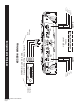
KX100.2 & KX200.4 Technical Manual Version 2.0 Page 5 Speaker Outputs High-Level Inputs SOURCE UNIT RIGHT + RIGHT LEFT LEFT + WARNING-Use Only One... Never Both At The Same Time!!! KX100.
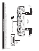
KX100.2 & KX200.4 Technical Manual Version 2.0 Page 6 Speaker Outputs RIGHT + RIGHT LEFT LEFT + SOURCE UNIT AMP 1 RCA Outputs *See note on page 7 if using High-Level inputs! High-Level Inputs WARNING-Use Only One... Never Both At The Same Time!!! KX200.
KX100.2 & KX200.4 Technical Manual Version 2.0 Page 7 Speaker Outputs SOURCE UNIT RIGHT + RIGHT LEFT LEFT + AMP 1 High-Level Inputs RCA Dummy Plugs AMP 2 LEFT + LEFT RIGHT RIGHT + When using both sets of High Level inputs, the supplied RCA dummy plugs must be inserted into the AMP 2 inputs in order for the fader to work properly.
Wiring cont. The use of twisted pair interconnects is recommended for all installations to minimize noise. When routing these cables through the automobile, try to keep them away from factory wiring harnesses and other power wiring. If you need to cross any of this wiring do so at a 90 degree angle to reduce the possibility for noise problems.
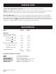
Fuse Ratings Model Fuse Size Wire Size KX75.2 KX150.4 15A 30A 8 GA 8 GA Specifications subject to change without prior notice. Adjusting Amplifier Controls On your Kicker amplifier there are rotary controls and switches on the end panel. These controls ensure the reliability and performance of the amplifier, so they need to be set correctly. If you are using a KX150.4 you will have two sets of rotary controls and switches. One set controls AMP1 and one set controls AMP2.
Adjusting Amplifier Controls cont. Crossover Control Where you set the crossover is very subjective and can be fine tuned to match your listening preference or speaker requirement. If the amplifier is driving small speakers (crossover set to HI PASS) this will eliminate the low frequencies from damaging the high frequency speaker. If the amplifier is driving subwoofers (crossover set to LO PASS). These are only guidelines because setting the right frequency depends on the listeners preferences.
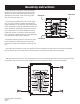
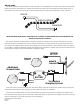
_ + - To Left Speaker 18" To Right Speaker BATTERY +12V or less FUSE GROUND - SIGNAL IN the amplifier to the speakers. switch to HI PASS. This will allow only high frequencies to pass through If the amplifier is driving speakers that do require a crossover, set the OR... speakers to play full range. the crossover switch may be set to the OFF position. This will allow the When the amplifier is driving speakers that do not require a crossover, KX100.
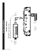
_ 4Ω Min. + KX100.2 & KX200.4 Technical Manual Version 2.0 Page 12 MONO GROUND BATTERY +12V FUSE To Woofer or less 18" REMOTE TURN-ON SPEAKER - SIGNAL IN to the woofers. This will allow only low frequencies to pass through the amplifier If the amplifier is used to drive subwoofers, set the switch to LO PASS. KX100.
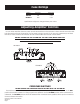
MONO SPEAKER LOW PASS CROSSOVER _ 4Ω Min. - - _ + HIGH PASS CROSSOVER HIGH PASS CROSSOVER To Right Speaker To Left Speaker RIGHT SPEAKER(S) 2Ω Min. 2Ω Min. LEFT SPEAKER(S) _ + + KX100.2 & KX200.4 Technical Manual Version 2.0 Page 13 To Woofer - BATTERY +12V or less 18" REMOTE TURN-ON GROUND sound quality. speakers to play in a dedicated frequency range for the best speakers will need a capacitor.
KX100.2 & KX200.4 Technical Manual Version 2.0 Page 14 - To Right Speaker To Left Speaker - + - - + - + + - + - To Left Speaker To Right Speaker - - BATTERY +12V or less 18" FUSE REMOTE TURN-ON GROUND SIGNAL IN AMP 1 SIGNAL IN AMP 2 the amplifier to the speakers. switch to HI PASS. This will allow only high frequencies to pass through If AMP 1 or AMP 2 are driving speakers that do require a crossover set the OR... speakers to play full range.
KX100.2 & KX200.4 Technical Manual Version 2.0 Page 15 - - - + To Right Speaker To Left Speaker + - + To Woofer - BATTERY +12V or less 18" FUSE REMOTE TURN-ON GROUND - SIGNAL IN AMP 1 SIGNAL IN AMP 2 to the woofers. This will allow only low frequencies to pass through the amplifier If AMP 2 is used to drive subwoofers, set the switch to LO PASS. AND... amplifier to the speakers. to HI PASS.
KX100.2 & KX200.4 Technical Manual Version 2.0 Page 16 - - To Left Speaker + - +12V or less 18" To Right Speaker FUSE REMOTE TURN-ON GROUND BATTERY + - SIGNAL IN AMP 1 SIGNAL IN AMP 2 a Y-Adapter. * The RIGHT input must be split up and fed to the L & R AMP 2 inputs with a Y-Adapter. * The LEFT input must be split up and fed to the L & R Amp 1 inputs with MAKE SURE: to the woofers.
Formulas Ohm’s Law E=IXR Where: E = Voltage (Volts) I = Current (Amps or Amperes) R = Resistance (Ohms or W) Formula Variations: I =E / R R=E/I Power Formula P=IXE Where: P = Power (Watts) I = Current (Amps or Amperes) E = Voltage (Volts) Formula Variations: I=P/E E=P/I P = I2 X R P = E2 / R Apply the numbers from the above formulas to the Power wire calculation to determine the minimum gauge wire to properly supply the amplifier with current. KX100.2 & KX200.4 Technical Manual Version 2.
Power Cable Calculation W) x 2 = (Total input wattage [Watts]) (Total RMS power output into 4W (Total input wattage) (Supply Voltage) = (Maximum input current [Amps]) Example: Amplifier with a rating of 100 watts per channel into 4 W 200 x 2 = 400 Watts (Total input power) 400 Watts / 12.5 Volts = 32 amps (Total maximum draw) Use this value of current draw to determine wire size from the chart below. Power Wire Chart Minimum Gauge wire Draw (Amps) Up to 4 ft. 4 to 7ft. 7 to 10ft. 10 to 13 ft.
ELETRONICS LIMITED WARRANTY Kicker warrants this product to be free from defects in material and workmanship under normal use for a period of THR EE ( 3) MON THS from date of original purchase with receipt. When purchased from a Authorized KICKER Dealer it is warranted for TWO (2) YEARS from date of original purchase with receipt.
P.O. Box 459 – Stillwater, Oklahoma 74076 – U.S.A. – 405 624-8510 or www.Kicker.