P/N 83-KRS100-001 September 2002 KRS-100 Nitrogen Releasing System Application, Operation and Maintenance Manual FM APPROVED UL Listing File No.
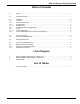
KRS-100 Nitrogen Releasing System Table of Contents 1-1 Scope ........................................................................................................................................ 1 2-1 General Description ................................................................................................................... 1 3-1 3-1.1 3-1.1 3-1.1.1 3-1.1.2 3-1.2 3-1.3 3-1.3.1 3-1.4 Installation ............................................................................................
KRS-100 Nitrogen Releasing System THIS PAGE INTENTIONALLY LEFT BLANK.
KRS-100 Nitrogen Releasing System KRS-100 NITROGEN RELEASING SYSTEM Application, Operation, and Maintenance of KRS-100 Pneumatic Releasing Device 1-1 SCOPE sure-operated switches can be installed on the KRS-100 actuation line. This manual is to be used in conjunction with the UL Listed and Factory Mutual Approved Kidde Industrial Dry Chemical Instruction Manual (P/N 220423) dated November 1998, and the Kidde Wet Chemical Instruction Manual (P/N 87122000-001) dated February 1997.
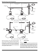
KRS-100 Nitrogen Releasing System 100 FT. MAX.- 1/4 INCH COPPER TUBING 50 FT. MAX. 1/4 INCH COPPER TUBING (3) THREE PRESSURE SWITCHES AND (10) TEN CYLINDERS VENT CHECK P/N WK-877810-000 (OPTIONAL) OUTLET APPROX. 2 1/2 INCHES IN DIA.
KRS-100 Nitrogen Releasing System The KRS-100 releasing device may be mounted either vertically (plumb) with the control head or actuator at the top, or horizontally (level), or at any angle between vertical and horizontal. 3-1.1 3-1.3 Connect actuation tubing to the outlet on the KRS-100 actuator valve body. Ream and thoroughly clean all chips and cutting oil from the inside of tubing prior to connection. All tubing is to be securely supported, no more than ten feet on centers.
KRS-100 Nitrogen Releasing System but bends must be made so that the tubing will not flatten or kink. A single coil of tubing approximately 2-1/2 inches in diameter is desirable at each flare or compression fitting. The coil may be neatly made by wrapping the tubing around any convenient cylindrical object of that diameter. 4-1 To demonstrate proper operation of the actuating system the following check-out is to be accomplished prior to installing the nitrogen cylinder (P/N 83-100004-001). 4-1.
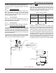
KRS-100 Nitrogen Releasing System 4. Install control head cover making sure notch in manual lever goes over manual release lever assembly. Secure with five screws supplied. 5. Ensure that safety pin is in place on the actuator valve assembly. If the pin cannot be placed in the actuator, verify that control head is SET. See Figure 2. 6. Remove and discard tensioning tools in gas valve and/ or electric shut-off and secure covers to units. 7. Turn on electric power and open main gas line shut-off valve.
KRS-100 Nitrogen Releasing System (THIS PAGE INTENTIONALLY LEFT BLANK) 83-KRS100-001 6 September 2002
LIMITED WARRANTY STATEMENT Kidde-Fenwal, Inc. represents that this product is free from defects in material and workmanship, and it will repair or replace any product or part thereof which proves to be defective in workmanship or material for a period of twelve (12) months from the date of purchase but not to exceed eighteen (18) months after shipment by Kidde-Fenwal Inc.