SIRIUS II 2, 4 & 8 ZONE CONVENTIONAL FIRE ALARM CONTROL PANEL INSTALLATION, OPERATION AND MAINTENANCE MANUAL TM0110 PROPRIETARY RIGHTS NOTICE The information contained in this manual is the property of Kidde Products Limited and may not be reproduced or transmitted in any form or by any means, electronic, mechanical, photocopying, recording or otherwise, nor stored in any retrieval system of any nature without the express written authority of Kidde Products Limited.
TABLE OF CONTENTS Chapter 1.0 2.0 3.0 4.0 5.0 Page Description 1.1 General Description 1.2 Display Panel 1.3 Indicators 1.4 Controls 1.5 EN54 Optional Functions With Requirements 1.6 Ancillary Functions Not Required By EN54 1.7 Internal Links 3 4 4 5 7 7 7 Operation 2.1 General 2.2 Time / Date 2.3 Day / Night Mode 2.4 Disablements 2.5 View 8 8 8 9 9 Installation and Commissioning 3.1 General 3.2 Installation 3.3 Circuit Connection Details 3.4 Commissioning 10 11 12 15 Maintenance 4.1 General 4.
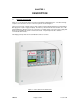
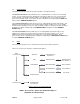
CHAPTER 1 DESCRIPTION 1.1 GENERAL DESCRIPTION Sirius II is a conventional fire alarm control panel designed to EN54 Parts 2 & 4. The Sirius II range comprises 2, 4 and 8 zone versions. An 8 zone panel is shown in Figure 1. The panel is housed in a metal enclosure and contains a main motherboard which is provided with a DC supply from a power supply unit (PSU).
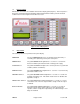
1.2 DISPLAY PANEL All indications and controls are available via the Sirius II display panel (Figure 2). This incorporates a two line by 16 character liquid crystal display with back light and this indicates panel fire and fault conditions and user and engineer menus when accessed. Figure 2: Sirius II Display Panel 1.
FIRE ALARM The red FIRE ALARM light comes on when any zone is in a fire alarm condition. This light flashes 1 second on 1 second off when a new zone fire alarm event occurs and is constant when accepted by operation of the silence/resound sounders switch. Operation of the panel reset switch turns this light off only if the alarm condition is removed. FIRE OUTPUT The red FIRE OUTPUT light comes on when the monitored and non monitored fire outputs are active.
The following controls are available in Access Level 2: SILENCE / RESOUND ALARMS If the panel has a zone fire state, operation of the SILENCE / RESOUND ALARMS switch silences all alarm devices, ALARM and ZONE fire lights stop flashing and stay on constantly and the buzzer sounds intermittently. If a new zone alarm condition occurs, the fire state conditions are re-enabled. Repeat operations of the switch toggles the panel between re-sounding and silencing of the external alarms and the panel buzzer.
1.5 EN 54 OPTIONAL FUNCTIONS WITH REQUIREMENTS The panel has the following optional functions: • Output to fire alarm devices. • Output to fire alarm routing equipment. • Delays to outputs. • Coincidence detection. • Alarm counter. • Test condition. • Two sounder circuits. 1.6 ANCILLARY FUNCTIONS NOT REQUIRED BY EN54 • Auxiliary change over contacts: -One change over contact operating on any fire condition. -One change over contact operating on any fault condition. • One auxiliary power supply output.
CHAPTER 2 OPERATION 2.1 GENERAL Under normal operating conditions, the green POWER ON light is on and the zone window lights are off. When a fire condition is detected, the applicable red zone fire light flashes, the red ALARM light flashes, the red FIRE OUTPUT light comes on, the alarm sounder circuits are activated (unless programmed off) and the buzzer on the panel sounds continuously.
2.4 DISABLEMENTS The disablement function allows the operator to disable several panel functions. The ZONE DISABLEMENT function allows the user to enable/disable one or more zone monitoring circuits. If a zone monitoring circuit is disabled, the panel ignores that zone’s fire, short circuit fault, open circuit fault or head removed fault conditions. The disabled zone does not affect any of the other zone monitoring circuits.
CHAPTER 3 INSTALLATION AND COMMISSIONING 3.1 GENERAL Installation of the fire detection and alarm system must comply with all applicable national and local regulations, standards and working practices. Take care not to install cables in the proximity of high voltage cables or in areas likely to induce electrical interference. Junction boxes should be avoided, but if they have to be installed then they must clearly be labelled "Fire Alarm". Refer to Figure 4 for the External Wiring Diagram.
Static discharges can be reduced by following these guidelines: 1. Always use conductive or anti-static containers for transportation and storage. 2. Wear an earth wrist strap while handling, ensuring a good earth connection is maintained. 3. Never subject a static sensitive device to a sliding movement over any surface and avoid any direct contact with the pins. 4. Avoid placing sensitive devices on plastic or vinyl surfaces. 5. Minimise the handling of sensitive devices and PCBs. 3.
last device in each of the zone wirings, end of line resistors across auxiliary alarm circuits and fire outputs. Connect all field devices. Once any field bases or devices are connected, DO NOT USE a high voltage Megger on the circuitry; low voltage multimeters may be used. Verify using a multimeter that all zone, auxiliary alarm circuit and fire output end of line capacitors and resistors can be seen.
polarised. Non-polarised sounders will show a sounder fault. The most common sounders are bells and electronic sounders. The same type of sounder must be used throughout the building and it must be distinctive so that the sound associated with a fire alarm is easily recognised. The voltage drop on each alarm circuit should be calculated to ensure that the minimum voltage at the end of each circuit exceeds the minimum required by each sounding device.
Figure 4: External Connections TM0110 Page 14 of 22 Issue 1.
3.4 COMMISSIONING CAUTION The control panel may be damaged by removing and/or inserting cards, modules, or interconnecting cables while the unit is energised. Do not attempt to install, service or operate this panel until this manual is read and understood.
Turn the mains supply off. Using the short lead supplied, connect the positive terminal of one battery to the negative terminal of the other battery. Connect the red battery lead to the free + battery terminal. Turn the mains on and connect the black battery lead to the free - battery terminal. After a few seconds, with the batteries connected, ALL lights should be off with the exception of the POWER ON light.
ZONE ONE MAN TEST The ZONE ONE MAN TEST function allows the engineer to test zone FIRE responses from one or more zones remotely from the panel. An engineer can put the zone into test and remotely trigger a detector or manual call point into fire. When in fire all panel alarm devices operate but the fire outputs do not operate. After 3 seconds the alarms turn off and the panel resets automatically.
PANEL ALARM MODES The PANEL ALARM MODES function allows the engineer to configure the panel alarm circuits. When the panel is in an alarm state, the alarm circuits can either be steady on or sound intermittently.
CHAPTER 4 MAINTENANCE 4.1 GENERAL Maintenance of equipment external to the control panel will be detailed in the appropriate manufacturer's literature. The back-up batteries are maintenance free but should be replaced every 4 years. CAUTION Risk of explosion if battery is replaced by an incorrect type. Dispose of batteries in accordance with all local regulations and the manufacturer’s instructions. All printed circuit boards are self-monitoring and therefore should only be replaced as required. 4.
CHAPTER 5 SPECIFICATIONS AND DATA 5.1 WIRING SPECIFICATION All system wiring should be screened and installed to meet local regulations. CABLE TYPES AND LIMITATIONS To shield the panel from outside interference and ensure compliance with electromagnetic regulations, we recommend screened cables are used throughout the installation. MAINS WIRING The requirements for the mains supply to the fire alarm panel is fixed wiring, using three core cable (no less than 0.75 sq mm and no more than 2.
Power Supply Mains supply voltage 230V AC +/- 10% 50/60 Hz Internal power supply 28V DC Nominal Output Voltage range 19V – 30V Ripple Voltage 500 mV 10 kHz bandwidth Total output current limited to 2.5 A Supply and battery charger monitored YES Batteries monitored YES Max battery size and Type 2 Yuasa NP7-12 12V 7 Ah SLA connected in series* Mains Fuse 240V 3.15A (T) anti-surge Battery fuse 2.
Maximum total sounder load Up to 500 mA each circuit (limit to 1A total) Maximum cable length per circuit 450 metres Maximum line resistance 22 Ω Maximum number of bells @ 25 mA each 40 (must be polarised and suppressed) Maximum number of sounders @ 20 mA each 50 (must be polarised) Fire Output 1 Number of circuits 1 End of line resistor value 6K8 5% 0.