
Manual


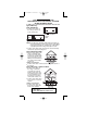


10. Position smoke alarm to mounting plate and turn clockwise to
lock into place. For tamper-resist, use long-nosed pliers to
remove thin plastic from notch on smoke alarm edge. Insert
pin into notch on edge of smoke alarm after smoke alarm is
positioned properly in base.
11. Remove arrow tab and close battery door. Smoke alarm may
beep briefly as door is closed.
12. Turn on power at main fuse box or circuit breaker.
13. Test smoke alarm. See “TESTING THE SMOKE ALARM.”
INTERCONNECTING SMOKE ALARMS
• This smoke alarm may be interconnected with as many as 11
other Firex model FADC, AD, ADC, PAD or FX1218 smoke
alarms, and as many as 6 Firex model ADH heat alarms for a
total of not more than 18 interconnected devices. DO NOT con-
nect to any other type or model smoke alarm.
• Connect smoke alarms to a single AC branch circuit. If local codes
do not permit, be sure the neutral wire is common to both phases.
LED INDICATOR(S)
Model FADC features one combined LED indicator. The following
section explains what condition the LED indicator is describing:
• Constant GREEN on - AC power is present
• GREEN is off - AC power is NOT present
• RED blinks once a minute - testing for presence of good
battery
• RED blinks once a second - smoke alarm senses smoke
and simultaneously sounds
an alarm
• RED blinks once every 10 - smoke alarm is quieting an
seconds unwanted alarm (Models
ADC and FADC only)
• RED is off and detector in alarm - another smoke alarm in the
(interconnected systems only) network has sensed smoke
and is signaling this alarm.
Item 4718 only
• RED blinks 3 times every minute - indicates this unit initiated an alarm
in an interconnected system
(press the test button to reset).
• RED blinks 4 times every minute - indicates weak or improperly
preceded by an audible chirp connected battery.
WHITE WHITE WHITE
YELLOW YELLOW
BLACK BLACK BLACK
TO GROUND
TO 120 VAC
Insert pin here
7
Remove pin from here
110-1082B 12/12/06 4:01 PM Page 7