M A G N O L I A P L AY S Y S T E M – F 2 3 2 9 0 INSTALLATION AND OPERATING INSTRUCTIONS WARNING To reduce the risk of serious injury or death, you must read and follow these instructions. Keep and refer to these instructions often and give them to any future owner of this play set. Manufacturer contact information provided below. OBSTACLE FREE SAFETY ZONE -26’ 5” x 25’7” area requires Protective Surfacing. See page 3.
Warnings and Safe Play Instructions CONTINUOUS ADULT SUPERVISION REQUIRED. Most serious injuries and deaths on playground equipment have occurred while children were unsupervised! Our products are designed to meet mandatory and voluntary safety standards. Complying with all warnings and recommendations in these instructions will reduce the risk of serious or fatal injury to children using this play system.
Protective Surfacing - Reducing Risk of Serious Head Injury From Falls One of the most important things you can do to reduce the likelihood of serious head injuries is to install shock-absorbing protective surfacing under and around your play equipment. The protective surfacing should be applied to a depth that is suitable for the equipment height in accordance with ASTM F1292.
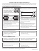
Instructions for Proper Maintenance Your Big Backyard Play System is designed and constructed of quality materials with your child’s safety in mind. As with all outdoor products used by children, it will weather and wear. To maximize the enjoyment, safety and life of your Play Set, it is important that you, the owner, properly maintain it. Check the following at the beginning of the play season: SWING HANGERS: Check that they are secure and orientated correctly.
About Our Wood Solowave Design™ uses only premium playset lumber, ensuring the safest product for your children’s use. Although great care has been taken in selecting the best quality lumber available, wood is a product of nature and susceptible to weathering (changes in the aesthetics of the wood). A light sanding may be required to remove minor splinters. For your information, we have described some changes that may occur as a result of weathering: 1.
Keys to Assembly Success Tools Required Shovel Measuring Tape Drill (1/8” 3/16” Bit) Safety Glasses Hammer Part Identification Key On each page, you will find the parts and quantities required to complete the assembly step illustrated on that page. Here is a sample. Ratchet 1/2”, 7/16” & 9/16” Level #2 & #3 Phillips or Robertson Square Ruler Step Ladder 2X 1234 Post 2 x 4 x 83” Symbols Throughout these instructions symbols are provided as important reminders for proper and safe assembly.
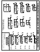
5/16" (8mm) Flat Washer 1/4" (6mm) Lock Washer 5/16" (8mm) T-Nut 1/4" (6mm) T-Nut 1/4" (6mm) Flat Washer 5/16" (8mm) Flat Washer For example: BOLT LENGTH 4½ (4.5) inches long 1 inch = 25.4mm LENGTH CONVERSION 0.31 inches x 25.4mm = 8mm BOLT DIAMETER 5/16 (0.31) inches For example: 1 inch = 25.4mm DIAMETER CONVERSION HARDWARE LENGTH CHART inches vs millimetres 6 152 5½ 140 5 127 114 4½ 4 102 3½ 89 3 76 2½ 64 2 51 1½ 38 1¼ 32 1-1/8 29 1 25.4 7/8 22 3/4 19 1/2 12.
63.5 2 1/2" 5/4 x 3 88.9 3 1/2" 5/4 x 4 114.3 4 1/2" 5/4 x 5 139.7 5 1/2" 5/4 x 6 88.9 3 1/2" 4x4 38.1 1 1/2" 34.9 1 3/8" 34.9 1 3/8" 38.1 1 1/2" 38.1 1 1/2" 2x6 136.5 5 3/8" 2x4 85.7 3 3/8" 2x3 63.5 2 1/2" 2 x2 15.9 5/8" 82.6 3 1/4" 34.9 1 3/8" 60.3 2 3/8" 85.7 3 3/8" 114.3 4 1/2" 136.5 5 3/8" 1/2 x 4 1x2 1x3 1x4 1x5 1x6 LENGTH CONVERSION 1 inch = 25.4mm 59.25 inches x 25.4mm = 1505mm For example: BOARD LENGTH 59¼ (59.25) inches 15.9 5/8" 15.9 5/8" 15.9 5/8" 15.
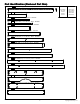
Part Identification (Reduced Part Size) 26pc. - 0517 Cedar Roofing (3/8 x 3-1/2 x 48") - Box 2 - 3630517 Nominal Size ⅜" x 3½" ½" x 4" 1" x 2" 1" x 4" 1" x 5" 6pc. - 1503 Wall Board (1/2 x 4 x 20") - Box 2 - 3631503 Actual Size ⅝" x 3½" " x 3¼" ⅝" x 1⅜" ⅝" x 3⅜" ⅝" x 4½" 7/16 1pc. - 1239 Picket (1 x 2 x 23-1/2") - Box 2 - 3641239 1pc. - 0726 Panel Frame (1 x 2 x 25-1/2") - Box 2 - 3640726 1pc. - 0705 Cedar Wall (1 x 4 x 23-1/2") - Box 2 - 3630705 1pc.
Part Identification (Reduced Part Size) 2pc. - 1853 Cedar Gap Board (1 x 5 x 38-3/4") - Box 2 - 3631853 Nominal Size Actual Size 1" x 5" 1" x 6" ⅝" x 4½" ⅝" x 5⅜" 2pc. - 1881 CE Centre Gap Board (1 x 5 x 38-3/4") - Box 2 - 3631881 1pc. - 1883 Front Ground (1 x 5 x 46-5/8") - Box 2 - 3641883 1pc. - 1872 Ground (1 x 5 x 75-5/8") - Box 2 - 3641872 2pc. - 0515 Top (1 x 6 x 13 1/2") - Box 2 - 3640515 2pc. - 0631 CE Rock Board (1 x 6 x 19-3/4") - Box 2 - 3630631 3pc.
Part Identification (Reduced Part Size) 2pc. - 0516 Bottom Arch (1 x 6 x 24") - Box 2 - 3640516 Nominal Size Actual Size 1" x 6" x 4" 2" x 2" 2" x 3" 2" x 4" ⅝" x 5⅜" 1" x 3½" 1½" x 1½" 1⅜" x 2½" 1⅜" x 3⅜" 5/4" 5pc. - 0318 Ground Stake (1-1/4 x 1-1/2 x 14") - Box 1 - 3650318 1pc. - 0403 Gusset (5/4 x 4 x 18-1/2") - Box 2 - 3640403 1pc. - 1886 Short Table Top (5/4 x 4 x 24") - Box 2 - 3641886 1pc. - 1887 Long Table Top (5/4 x 4 x 41-1/4") - Box 2 - 3641887 1pc.
Part Identification (Reduced Part Size) 1pc. - 4919 SW Rail Block (2 x 4 x 5-3/8") - Box 2 - 3644919 Nominal Size Actual Size 2" x 4" 2" x 6" 1⅜" x 3⅜" 1½" x 5⅜" 1pc. - 1861 SW Mount (2 x 4 x 38-1/8") - Box 2 - 3641861 1pc. - 1856 SW Upright (2 x 4 x 48-5/16") - Box 2 - 3641856 1pc. - 1885 Centre Post (2 x 4 x 79-5/8") - Box 2 - 3641885 2pc. - 1863 SW Post (2 x 4 x 86-11/16") - Box 2 - 3641863 4pc. - 1500 Post (2 x 4 x 83") - Box 2 - 3641500 1pc.
Hardware Identification (Actual Size) 4pc. LS1 - Lag Screw 1/4 x 1-1/2" - (9262212) 10pc. LS3 - Lag Screw 1/4 x 3" - (9262230) 1pc. H1 - Hex Bolt 1/4 x 1-1/2" - (9277212) 20pc. H2 - Hex Bolt 1/4 x 2" - (9277220) 4pc. H3 - Hex Bolt 1/4 x 2-1/2" - (9277222) 2pc. H4 - Hex Bolt 1/4 x 4" - (9277240) 1pc. H8 - Hex Bolt 1/4 x 4-1/4" - (9277241) 5pc. H5 - Hex Bolt 1/4 x 4-1/2" - (9277242) 4pc. H7 - Hex Bolt 1/4 x 5-1/2" - (9277252) 13 support@solowavedesign.
Hardware Identification (Actual Size) 4pc. G2 - Hex Bolt 5/16 x 1" - (9277310) 4pc. G1 - Hex Bolt 5/16 x 1-1/2" - (9277312) 2pc. G8 - Hex Bolt 5/16 x 2" - (9277320) 5pc. G4 - Hex Bolt 5/16 x 4" - (9277340) 5pc. G5 - Hex Bolt 5/16 x 4-1/2" - (9277342) 14 support@solowavedesign.
Hardware Identification (Actual Size) 38pc. TN1 - 1/4" T - Nut -(9285200) 44pc. FW3 - #8 Flat Washer - (9251500) 18pc. LW2 - 5/16" Lock Washer - (9253300) 17pc. FW0 - 3/16" Flat Washer - (9251100) 43pc. LW1 - 1/4" Lock Washer - (9253200) 18pc. TN2 - 5/16" T- Nut - (9285300) 52pc. FW1 - 1/4" Flat Washer - (9251200) 2pc. LN4 - #12 Lock Nut - (9289600) 5pc. BN1 - 1/4" Barrel Nut - (9248200) 2pc. LN2 - 5/16" Lock Nut - (9283300) 22pc. FW2 - 5/16" Flat Washer - (9251300) 2pc.
Part Identification (Reduced Part Size) 1X 3310148 Slide 48" High Rail -Green 1X 3320190 Stool Seat Set 1X 3320386 Rocks (5pk) 3-Green 2-Yellow 1X 3202001 Swing Hanger Bolt Thru. (6 pk) 1X 3201103 (4 Pk) Corner Brace Set 1X 3200184 Triangle Plate (4pk) Green 1X 3320356 Big Backyard I.
Step 1: Inventory Parts - Read This Before Starting Assembly STOP A. STOP STOP STOP his is the time for you to inventory all your hardware, wood and accessories, T referencing the parts identification sheets. This will assist you with your assembly. • The wood pieces will have the four digit key number stamped on the ends of the boards. The wood pieces are referenced throughout the instructions with this number. • Please refer to Page 6 for proper hardware assembly.
Step 2: Rock Wall Assembly Fig. 2.1 0630 0630 S2 0606 0631 0631 0630 0349 Note: Gaps between boards 2-1/4”, not to exceed 2-3/8” Note: The holes in the rock boards must orient to the top of the boards. 7-3/4” Approx A: Lay 2 (0349) Rock Rails down, side by side with angled edges facing down. (fig. 2.1) B: Place (0606) CE Access Board on the bottom of each (0349) Rock Rail as shown in fig. 2.1. Make sure (0606) CE Access Board is flush to the outside and bottom edges of each (0349).
Step 3: Swing Beam Assembly Warning: For your child’s safety, orientate the swing hangers as shown to ensure your swing will have proper swing motion when installed. Failure to do so could result in premature failure of the swing hanger or swing chain. Fig. 3.4 Make sure triangle is tight against beam B: In the end holes of (1826) Front Beam install 4 BoltThru Swing Hangers (fig. 3.1) making sure the swing hangers are oriented in the direction shown in fig. 3.4 to maintain proper swing motion.
Step 4: Swing End Assembly A: Attach 2 (1863) SW Posts to (1856) SW Upright using 2 (G4) 5/16 x 4” Hex Bolts (with lock washer, flat washer and t-nut). (fig. 4.1) Fig. 4.1 5/16” Lock Washer G5 1863 1862 5/16” Flat Washer 1856 5/16” T-Nut 5/16” T-Nut 5/16” Flat Washer 5/16” Lock Washer G5 G4 1863 B: Attach (1862) SW Support to both (1863) SW Posts and (1856) SW Upright using 3 (G5) 5/16 x 4-1/2” Hex Bolts (with lock washer, flat washer and t-nut). (fig. 4.
Step 5: Attach Swing End to Swing Beam A: Place (4919) SW Rail Block in the centre between (1826) Front Beam and (1825) Back Beam and attach with 1 (H8) 1/4 x 4-1/4” Hex Bolt (with lock washer, flat washer and t-nut). (fig. 5.1 & 5.2) 1826 Fig. 5.1 H8 Fig. 5.2 1/4” Lock Washer 1825 1826 4919 1/4” Flat Washer 1825 1/4” T-Nut B: Attach Swing Beam Assembly to the side of the Swing End Assembly with the overhang (fig. 5.3 & 5.
Step 6: Roof Assembly Part 1 A: Attach 1 (0863) Roof Support to another at the peak using 1 (S4) #8 x 3” Wood Screw. Do this twice so you have 2 Roof Support Assemblies. (fig. 6.1 & 6.2) B: Attach 1 (0501) Joist to another at the peak using 1 (S4) #8 x 3” Wood Screw. (fig. 6.1) C: Place the Roof Supports and Roof Joist Assemblies in the pattern shown in fig. 6.1 Step * ** S4 Fig. 6.1 Fig. 6.
Step 6: Roof Assembly Part 2 D: Starting at the top of the Roof Support Assembly and working down attach 3 (0517) Cedar Roofing on one side of the (0863) Roof Supports and (0501) Joists with 3 (S0) #8 x 7/8” Truss Screws per board. (fig. 6.3 and 6.5) Be sure to overlap the Cedar Roofing as shown in fig. 6.4. E: Repeat Step A for the other side of the Roof Support Assembly. * ** F: Drill a hole 1-1/4” above the factory drilled holes in 2 (0517) Cedar Roofing.
Step 7: Side Wall Assembly A: On the ground lay flat two (1500) Posts then attach (1874) Side Ground with 4 (H2) 1/4 x 2” Hex Bolts (with lock washer, flat washer and t-nut); (1501) Floor End using 2 (H2) 1/4 x 2” Hex Bolts (with lock washer, flat washer and t-nut) in the bottom holes, noticing hole locations; and (1864) SL Roof Side with 2 (H2) 1/4 x 2” Hex Bolts (with lock washer, flat washer and t-nut) as shown in fig. 7.1.
Step 8: Swing Wall Assembly A: Attach (1872) Ground using 4 (H2) 1/4 x 2” Hex Bolts (with lock washer, flat washer and t-nut); (1501) Floor End (in the bottom holes), (1502) Wall Support and (1865) SW Roof Side using 2 (H2) 1/4 x 2” Hex Bolts (with lock washer, flat washer and t-nut) for each board to two (1500) Posts. (fig. 8.1) Note: Keep all bolts loose.
Step 9: Back Wall Assembly A: On the back side of the assembly, attach (0799) Floor Back to both (1500) Posts using 2 (H5) 1/4 x 4-1/2” Hex Bolts (with lock washer, flat washer and t-nut) The bolt on the Side Wall should be installed from the inside of the assembly. (fig. 9.1) The middle bolt hole should be towards the bottom. B: Attach (1855) Divider to (0799) Floor Back with 1 (H1) 1/4 x 1-1/2” Hex Bolt (with lock washer, flat washer and t-nut). (fig. 9.1).
Step 10: Front Wall Assembly A: On the front side of the assembly, attach (0799) Floor Back to both (1500) Posts using 2 (H5) 1/4 x 4-1/2” Hex Bolts (with lock washer, flat washer and t-nut). (fig. 10.1) The middle bolt hole should be towards the bottom. Note: Pre-drill all holes using a 1/8” drill bit before installing the lag screws.
Step 11: Attach Gussets Note: Pre-drill all holes using a 1/8” drill bit before installing the lag screws. A: Make sure the assembly is square before proceeding. B: Attach (0403) Gusset to (1500) Post on the front Swing Wall side using 1 (LS3) 1/4 x 3” Lag Screw (with flat washer). The other end of the gusset should be tight against (0799) Floor Back. (fig. 11.
Step 12: Attach Lower Diagonals Pre-drill all holes using a 1/8” drill bit before installing the lag screws. A: Attach 1 (0369) Lower Diagonal to each end of (1872) Ground with 1 (H2) 1/4 x 2” Hex Bolt (with flat washer, lock washer and t-nut) per side. (fig. 12.1) Make sure to keep the bolts loose. B: Through the pre-drilled holes attach (0369) Lower Diagonals to each (1500) Post using 1 (LS3) 1/4 x 3” Lag Screw (with flat washer) per diagonal. (fig. 12.1) Tighten the Hex Bolts from Step A. Fig. 12.
Step 13: Floor Frame Assembly A: Remove the middle and bottom bolts in (1861) SW Mount. Do not discard these bolts, you will re-install them after the (0790) Floor Joist is attached. (fig. 13.1) B: From inside of the assembly, measure 2” down from the top of each (1501) Floor End (fig. 13.2) and then attach (0790) Floor Joist to each board in the top pilot holes with 2 (S4) #8 x 3” Wood Screws per end. (fig.13.2) C: Reinstall the bolts in (1861) SW Mount and tighten all three bolts. (fig. 13.
Step 14: Attach Gap and Floor Boards A: Place one (1853) Cedar Gap Board at each end of the assembly; two (1881) CE Centre Gap Board in the middle so the gaps in the boards fit around the (1885) Centre Post; and six (1851) Cedar Floor Boards in between the Gap and Centre Boards. Make sure all boards are evenly spaced. (fig. 14.1) B: Attach all boards to (0795) Side Joist, (0790) Floor Joist and (1882) Short Joists with 5 (S2) #8 x 1-1/2” Wood Screws per board. (fig. 14.1) Fig. 14.
Step 15: Swing Side Wall Assembly A: In between both (1500) Posts on Swing Wall side attach six (1503) Wall Boards to (1501) Floor End and (1502) Wall Support using 4 (S0) #8 x 7/8” Truss Screws per board. Make sure the bottom of the boards are tight against the floor boards and bevelled edges are facing out and are at the top of the boards. The distance between boards should be evenly spaced, not exceeding 1-13/16”. (fig. 15.1 and 15.
Step 16: Chalk Wall Frame Assembly A: On the back of the assembly, attach (0726) Panel Frame to (1500) Post using 2 (S2) #8 x 1-1/2” Wood Screws. The top of (0726) Panel Frame is tight to the bottom of (0358) Top Front Back. (fig. 16.1) B: Place (0705) Cedar Wall tight to the bottom of (0726) Panel Frame and attach to (1500) Post using 2 (S2) #8 x 1-1/2” Wood Screws. The bevelled edge faces the inside of the assembly, against (1855) Divider. (fig. 16.2) 0358 Fig. 16.1 1855 1500 Fig. 16.
Step 17: Attach Chalk Wall/Tarp to Fort A: On the back of the assembly, loosen the top bolt in (1855) Divider and place the Chalk Wall Tarp in between (1855) Divider and (0358) Top Front Back. (fig. 17.1) B: Attach Chalk Wall Tarp to (0358) Top Front Back, (0726) Panel Frame, (0705) Cedar Wall and (1855) Divider using 12 (S5) #8 x 1/2” Pan Screws (with #8 flat washer) as shown in fig. 17.1. The 2 screws on (1855) Divider are attached from the inside of the assembly. (fig. 17.
Step 18: Slide and Front Wall Frame Assembly A: On the Side Wall side of the assembly, attach (1851) Cedar Floor Board to both (1500) Posts, tight to the top of (1501) Floor End, using 4 (S2) #8 x 1-1/2” Wood Screws. (fig. 18.1) B: On the Front side of the assembly, attach (1239) Picket to (1500) Post and (1885) Centre Post, tight to the top of (0799) Floor Back, using 2 (S2) #8 x 1-1/2” Wood Screws. (fig. 18.
Step 19: Cafe Canopy Assembly A: Feed Cafe Frame A through the pockets of the Cafe Canopy on the long side. The end with the screw holes should be on the inside of the canopy. (fig. 19.1) B: Feed Cafe Frame B through the pockets of the shorter side of the Cafe Canopy. The end with the screw holes should line up with the screw holes on Cafe Frame A. (fig. 19.1) C: Attach both frames together with 2 (MB1) #12 x 1/2” Machine Bolt (with #12 lock nut). (fig. 19.2 and 19.3) Fig. 19.
Step 20: Attach Cafe Canopy to Fort Part 1 A: Remove the (S2) #8 x 1-1/2” Wood Screw on the (1885) Centre Post side of the (1239) Picket. (fig. 20.2) B: Place the Cafe Canopy on the fort so Cafe Frame A (longer side) is on the Side Wall side and Cafe Frame B (shorter side) is on the Front side of the fort. (fig. 20.1) C: The distance from the bottom of Cafe Frame B to the bottom of (1239) Picket should be 7/16”. (fig. 20.3) Cafe Frame B Fig. 20.3 1885 Fig. 20.
EXTRA IMAGES!!!!!! Step 20: Attach Cafe Canopy to Fort Part 2 Pre-drill holes using a 1/8” drill bit before installing the (S6) #12 x 1” and (S7) #12 x 2” Pan Screws. A E: Attach Cafe Frame A to (1501) Floor End with 2 (S6) #12 x 1” Pan Screws (fig. 20.5 and 20.6) and Cafe Frame B to (1239) Picket with 1 (S7) #12 x 2” Pan Screws. (fig. 20.7) Fig. 20.
Step 21: Side Wall Window Assembly Part 1 A: Tight to the bottom of (1864) SL Roof Side, with the arch facing down, attach (1884) Side Top to both (1500) Posts with 4 (S2) #8 x 1-1/2” Wood Screws. (fig. 21.1) B: Tight to the top of the (1851) Cedar Floor Board, which the Cafe Canopy is attached to, attach 2 more (1851) Cedar Floor Boards to both (1500) Posts with 4 (S2) #8 x 1-1/2” Wood Screws per board. The boards should be tight to each other. (fig. 21.1) Fig. 21.
Step 21: Side Wall Window Assembly Part 2 C: Measure 4-1/2” from the top of (1864) SL Roof Side and tight to both (1500) Posts attach 2 (0702) CE Wall Boards, with bevelled edges facing out and at the top of the boards, to (1884) Side Top and the middle (1851) Cedar Floor Board using 4 (S1) #8 x 1-1/8” Wood Screws per board. (fig. 21.2 and 21.
Step 22: Front Wall Window Assembly A: Tight to the top of the (1880) CE Wall Board, which the Cafe Canopy is attached to, attach 2 more (1880) CE Wall Boards to (1500) Post and (1885) Centre Post with 4 (S2) #8 x 1-1/2” Wood Screws per board. The boards should be tight to each other. (fig. 22.
Step 23: Attach Ground Stakes MOVE FORT TO FINAL LOCATION. FINAL LOCATION MUST BE LEVEL GROUND Warning! To prevent tipping and avoid potential injury, stakes must be driven 10-1/2” into ground. Digging or driving stakes can be dangerous if you do not check first for underground wiring, cables or gas lines. A: Drive 2 (0318) Ground Stakes 10-1/2” into the ground at both ends of (1872) Ground into each (0369) Lower Diagonal as shown in fig. 23.1.
Step 24: Roof Frame Assembly A: Attach 1 (0357) Tarp Front Back to each end of (1864) SL Roof Side and (1865) SW Roof Side, making sure the pilot holes are centred on the end of each Roof Side, with 4 (S2) #8 x 1-1/2” Wood Screws per (0357) Tarp Front Back. (fig. 24.1 and 24.2) B: At all 4 corners centre and attach 1 Corner Brace using 3 (S5) #8 x 1/2” Pan Screw per brace as shown in fig. 24.1 and 24.3. Corner Brace Fig. 24.1 Fig. 24.
Step 25: Attach Roof to Fort A: With two helpers place the Roof Assembly, from Step 6, on the fort as shown in fig. 25.1. The roof should be centred on the assembly and (0863) Roof Supports should be flush to the inside of the fort and resting on (1865) SW Roof Side and (1864) SL Roof Side. The (0501) Joists should fit tight to the inside of each (0357) Tarp Front Back.
Step 26: Attach Roof Arches A: From inside the Roof Assembly, on each opening, place 1 (0515) Top tight to the top of each (0863) Roof Support using 4 (S2) #8 x 1-1/2” Wood Screws per board. (fig. 26.1 & 26.2) B: Tight to the bottom of each (0515) Top attach 1 (0516) Bottom Arch to each (0863) Roof Support using 4 (S2) #8 x 1-1/2” Wood Screws per board. (fig. 26.1 & 26.2) Fig. 26.2 S2 x 8 Fig. 26.
Step 27: Attach Wall Canopy A: Loosen the 4 bolts indicated in fig. 27.1 then tuck the Wall Canopy between the posts and (1872) Ground, down to the top of the bolts. B: Measure 19” up from the top of (1872) Ground and attach (1658) Safety Rail to both (1500) Posts with 4 (S2) #8 x 1-1/2” Wood Screws. (1658) Safety Rail should overlap the Wall Canopy by 1”. (fig. 27.1 and 27.
Step 28: Short and Long Table Top Assemblies A: Place (1887) Long Table Top on (1868) Table Support so the end with the shorter notch is flush to one end of (1868) Table Support. Also, the notched out edge of (1887) Long Table Top is flush to the face of (1868) Table Support as shown in fig. 28.1. Attach boards together using 5 (S7) #12 x 2” Pan Screws through (1868) Table Support.
Step 29: Attach Wrap Around Canopy A: Loosen the bolts attaching (1883) Front Ground to (1885) Centre Post and (1500) Post and the bolts attaching (1874) Side Ground to both (1500) Posts then tuck the Wall Canopy between the posts and ground boards, down to the top of the bolts. (fig. 29.
Step 30: Attach Table Top Assemblies to Fort A: Place Long Table Top assembly notches tight against both (1500) Posts, so it overlaps the Wrap Around Canopy by 1”. Attach assembly through (1868) Table Support to each post using 2 (S3) #8 x 2-1/2” Wood Screws per post. Make sure the screws are attached to the posts at the top edge of the tarp. (fig. 30.1 and 30.2) B: Place Short Table Top assembly tight to the bottom of Long Table Top assembly at (1500) Post and against (1885) Centre Post.
Step 31: Attach Wrap Around Canopy to Table Supports A: From the inside of the assembly and 1/2” down from the edge of the canopy attach Wrap Around Canopy to (1888) Front Table Support with 2 (S5) #8 x 1/2” Pan Screws (with #8 flat washer) and to (1868) Table Support with 3 (S5) #8 x 1/2” Pan Screws (with #8 flat washer). (fig. 31.1) Fig. 31.1 1868 1888 S5 with #8 flat washer Hardware 5x S5 #8 x 1/2” Pan Screw (#8 flat washer) 50 support@solowavedesign.
Step 32: Attach Components to Fort Part 1 Note: Pre-drill all holes using a 1/8” drill bit before installing the (S7) #12 x 2” Pan Screws. A: Place Slide centred between (1885) Centre Post and (1500) Post. (fig. 32.1 and 32.2) B: Attach slide to fort through the (0799) Floor Back using 3 (S7) #12 x 2” Pan Screws. (fig. 32.2) C: On the front of the assembly attach the Flower Box, centred, to the top (1880) CE Wall Board with 2 (S5) #8 x 1/2” Pan Screws as shown in fig. 32.1 and 32.3. Fig. 32.1 Fig.
Step 32: Attach Components to Fort Part 2 D: At the corner of the Wrap Around Canopy, on (1500) Post, attach the Phone Holder with 2 (S6) #12 x 1” Pan Screws. (fig. 32.4 and 32.5) E: Attach one end of the Phone Cord to the Phone Holder and the other end to the base of the Phone. (fig. 32.5) F: Place Phone in the Phone Holder. Fig. 32.4 Fig. 32.5 1500 Phone 1500 S6 Phone Holder Phone Cord Hardware 2x S6 #12 x 1” Pan Screw 52 Other Parts 1 x Phone Assembly support@solowavedesign.
Step 33: Attach Rock Rail to Fort Note: Pre-drill all holes using a 1/8” drill bit before installing the (S15) wood screws. A: Place Rock Wall Assembly from Step 2 centred on and flush to top of (0799) Floor Back (fig. 33.1 and 33.3). Attach (0349) Rock Rails to (0799) Floor Back using 4 (S15) #8 x 1-3/4” Wood Screws as shown in fig. 33.2. B: Attach (0606) CE Access Board to top of Rock Wall Assembly, flush to top of (0349) Rock Rail using 4 (S2) #8 x 1-1/2” Wood Screws. (fig. 33.4) Fig. 33.1 Fig. 33.
Step 34: Stool Seat Assembly A: Using the hardware provided with the Stool Seat Assembly attach 1 Seat to 1 Seat Support and then create a second seat as in fig. 34.1. B: Keeping the Cross Brace tight to the Seat Assemblies, fasten the Cross Brace to each of the Seat Assemblies using the hardware provided. (fig. 34.2) 1/4-20 x 1” Machine Screw Fig. 34.1 1/4” Flat washer Seat Spacer Seat Support 1/4-20 Lock Nut Fig. 34.
Step 35: Attach Stool Seat and Flower Box to Fort A: Attach the Stool Seat Assembly to (1874) Side Ground using 2 (G2) 5/16 x 1” Hex Bolt (with lock washer, flat washer and t-nut) per Seat Assembly. (fig. 35.1 and 35.2) B: Attach a Flower Box, centred under the window on (1851) Cedar Floor Board with 2 (S5) #8 x 1/2” Pan Screws as shown in fig. 35.1 and 35.3. Fig. 35.3 Fig. 35.1 1851 S5 1851 Fig. 35.
Step 36: Attach Swing Assembly to Fort A: Attach Swing Assembly from Step 5 to (1861) SW Mount with 1 (G5) 5/16 x 4-1/2” Hex Bolt (with lock washer, flat washer and t-nut) and 1 (G8) 5/16 x 2” Hex Bolt (with 2 flat washers and 1 lock nut) as shown in fig. 36.1 and 36.2. 1861 Fig. 36.2 5/16” Flat Washers 5/16” T-Nut 5/16” Lock Washer G5 5/16” Lock Nut G8 Fig. 36.
Step 37: Attach Swing Ground Stakes A: Drive one (0318) Ground Stake 10-1/2” into the ground at each (1863) SW Post and attach with 2 (S3) #8 x 2-1/2” Wood Screws per ground stake. (fig. 37.1 and 37.2) Warning! To prevent tipping and avoid potential injury, stakes must be driven 10-1/2” into ground. Digging or driving stakes can be dangerous if you do not check first for underground wiring, cables or gas lines. S3 Fig. 37.2 1863 0318 Fig. 37.
Step 38: Attach Glider and Swings If Bolt protrudes beyond T-Nut Warning! Check entire play centre for bolts protruding beyond T-Nuts. Use extra washers to eliminate this condition. Use an extra Flat W asher A: Attach 2 Belt Swings and Acro Swing to the Bolt-Thru Swing Hangers. (fig. 39.1) Fig. 39.1 Acro Swing Belt Swings Other Parts 2 x Belt Swings 1 x Acro Swing 58 support@solowavedesign.
Final Step: Attach I.D. Plaque ATTACH THIS WARNING & I.D. PLAQUE TO A PROMINENT LOCATION ON YOUR PLAY EQUIPMENT! (Fort or Swing Post) This provides warnings concerning safety and important contact information. A Tracking Number is provided to allow you to get critical information or order replacement parts for this specific model.
NOTES NOTES 60 support@solowavedesign.
NOTES NOTES 61 support@solowavedesign.
BIG BACKYARD Consumer Registration Card First Name Initial Last Name Street Apt. No.