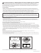
T W I N M O U N TA I N L O D G E – F 2 5 7 0 0 INSTALLATION AND OPERATING INSTRUCTIONS To reduce the risk of serious injury or death, you must read and follow these instructions. Keep and refer to these instructions often and give them to any future owner of this play set. Manufacturer contact information provided below. 30'-9" WARNING 18'-9" OBSTACLE FREE SAFETY ZONE -30’ 9” x 27’1” (9.37 x 8.23 m) area requires Protective Surfacing. See page 3. 11'-10" 27'-1" MAXIMUM VERTICAL FALL HEIGHT - 6’ 7” (2.
Warnings and Safe Play Instructions CONTINUOUS ADULT SUPERVISION REQUIRED. Most serious injuries and deaths on playground equipment have occurred while children were unsupervised! Our products are designed to meet mandatory and voluntary safety standards. Complying with all warnings and recommendations in these instructions will reduce the risk of serious or fatal injury to children using this play system.
Protective Surfacing - Reducing Risk of Serious Head Injury From Falls One of the most important things you can do to reduce the likelihood of serious head injuries is to install shock-absorbing protective surfacing under and around your play equipment. The protective surfacing should be applied to a depth that is suitable for the equipment height in accordance with ASTM F1292.
Instructions for Proper Maintenance Your Cedar Summit Play System is designed and constructed of quality materials with your child’s safety in mind. As with all outdoor products used by children, it will weather and wear. To maximize the enjoyment, safety and life of your Play Set, it is important that you, the owner, properly maintain it. Check the following at the beginning of the play season: GROUND STAKES (ANCHORS): Check for looseness, damage or deterioration.
About Our Wood Cedar Summit Premium Play Systems uses only premium playset lumber, ensuring the safest product for your children’s use. Although we take great care in selecting the best quality lumber available, wood is still a product of nature and susceptible to weathering which can change the appearance of your set.
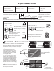
Keys to Assembly Success Tools Required • Tape Measure • Carpenters Level • Carpenters Square • Claw Hammer • Standard or Cordless Drill Part Identification Key On each page, you will find the parts and quantities required to complete the assembly step illustrated on that page. Here is a sample.
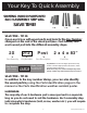
Your Key To Quick Assembly SORTING WOOD PARTS INTO EACH ASSEMBLY STEP WILL SAVE TIME! Step Step Step SAVE TIME - TIP #1: Open each box with wood parts and look for the Key Number stamped on the end of the wood part (see chart below). Sort each wood part into the different assembly steps.
202 Slide End Panel FSC 190 200 Roof Panel A FSC TNR3 Short Exit TNR 2 Slide Exit Top TNR3 Post Mount 9X TNR 2 Slide Elbow TNR 2 Slide RT Flange TNR 2 Slide LT Flange 10X TNR 2 Slide Clamp Ring Telescope with Mount 350 040 081 190 210 222 34 0 36 3 362 370 34 0 Door Window Panel FSC 042 010 Folding Bench FSC Sky Chalk Wall 133 Gable Clock Assembly 062 390 36 3 Narrow Front Panel FSC 120 Door Hardware 392 391 140 2X 3X Rebar Ground Stake x6 051 210 222 x2 Cedar Summ
2X 9 152 151 150 Heavy "L" Bracket X3 160 Heavy "C" Bracket DX Swing Hanger 6X 1X Acro 2X Acro Bar Handle 2X 20" Chain Maze N Wave 2.35m Slide 2X Swing Belt Seat 090 050 052 080 Flat Panel Bracket x5 13 1 Steel Hand Grip x2 I.
Part Identification (Reduced Size) (1) 023 - 1 x 4 x 21" - Ladder Gap FSC - Box 2 - 4598958 (4) 230 - 1 x 4 x 29" - Cedar Wall FSC - Box 3 - 4591975 (1) 072 - 1 x 4 x 35-5/8" - Floor Board FSC - Box 3 - 4599050 (1) 025 - 1 x 4 x 41-3/4" - RW - AL Support FSC - Box 2 - 4599062 (2) 394 - 1 x 5 x 7-1/8" - End Gable C FSC - Box 3- 4599047 (4) 363 - 1 x 5 x 10" - Sunburst Side FSC - Box 2 - 4599066 (2) 393 - 1 x 5 x 12-1/8" - End Gable B FSC - Box 3 - 4599046 (2) 392 - 1 x 5 x 17-1/8" - End Gable D FSC - Bo
Part Identification (Reduced Size) (1) - 390 - 1 x 6 x 34-15/16" - Fr Centre Gable FSC - Box 3 - 4599052 (1) 133 - 1 x 2 x 27-7/16" - Chalkwall Side FSC - Box 2 - 4599035 (2) 201 - 1 x 2 x 34-1/8" - Upright Crowsnest FSC - Box 3 - 4599072 (2) 212 - 3/4 x 3-1/4 x 14-3/4" - Crowsnest Side FSC - Box 2 - 4599042 (2) 210 - 3/4 x 5-1/4 x 14-3/4" - Crowsnest Bottom Side FSC - Box 3- 4599037 (1) 121 - 5/4 x 3 x 10" - Door Stop FSC - Box 2 - 4592715 (1) 081 - 5/4 x 3 x 33" - Half Wall Top FSC - Box 3 - 4599053 (1
Part Identification (Reduced Size) (1) 280 - 1-1/4 x 3 x 32-1/4" - TNR Ground Brace FSC - Box 2 - 4598963 (1) 360 - 1-1/4 x 3 x 34-1/2" - Back Gable Support FSC - Box 3 - 4599031 (1) 370 - 1-1/4 x 3 x 34-1/2" - Mid Gable Support FSC - Box 3 - 4599057 (2) 060 - 1-1/4 x 3 x 40-3/4" - Floor Joist FSC - Box 3 - 4592608 (4) 340 - 1-1/4 x 3 x 50-15/16" - Roof Rafter FSC - Box 3 - 4599059 (1) 071 - 1-1/4 x 3 x 63-1/4" - Long Floor Joist FSC - Box 3 - 4599056 (2) 062 - 1-1/4 x 3 x 72" - Roof Support FSC - Box
Part Identification (Reduced Size) (1) 151 - 2-1/2 x 3 x 15" - Block SW FSC - Box 3 - 4598507 (1) 150 - 2-1/2 x 3 x 15" - SW Block Angle FSC - Box 3 - 4599068 (1) 141 - 4 x 4 x 16" - SW Mount FSC - Box 3 - 4599069 (1) 160 - 2-1/2 x 3 x 51" - Support Cross FSC - Box 1 - 4599067 (2) 152 - 4 x 4 x 92" - SW Post FSC - Box 1 - 4599070 (1) 140 - 4 x 6 x 92" - Engineered SW Beam FSC - Box 1 - 4599049 1x - TNR 2 Slide Rt Flange (3310223) Yellow 1x - TNR 2 Slide Lt Flange (3310222) Yellow (1) 350 - 1-1/4 x 3
Part Identification (Reduced Size) (1) 040 - 1-1/4 x 37 x 92" Slide End Panel FSC Box 3 - 47598981 (1) 051 - 1-1/4 x 43 x 92" Front Wall Panel FSC Box 2 - 47598971 (1) 050 - 1-1/4 x 37 x 92" SW Wall Panel FSC Box 3 - 47599007 (1) 120 - 1-1/4 x 15-3/4 x 42-1/8" Door Window Panel FSC Box 2 47598977 (1) 010 - 2-13/32 x 6-3/4 x 34" 47592658 Folding Bench FSC - Box 2 (1) 052 - 1-1/4 x 43 x 92" Back Wall Panel FSC Box 2 - 47598970 (1) 041 - 1-1/4 x 21-1/2 x 92" Narrow Back Panel FSC - Box 2 - 47598992 14
Hardware Identification (Actual Size) (5) WB9 - Wafer Bolt 5/16 x 2-1/8" - (53613324) (7) WB7 - Wafer Bolt 5/16 x 3" - (53613330) (7) WB8 - Wafer Bolt 5/16 x 2-3/8" - (53613326) (4) WL3 - Wafer Lag 1/4 x 1-3/8" - (52613216) (7) WB10 - Wafer Bolt 5/16 x 2-5/8" - (53613330) (17) WL5 - Wafer Lag 1/4 x 2-1/2" - (52613222) (4) H1 - Hex Bolt 1/4 x 1-1/2" - (53703212) (1) H8 - Hex Bolt 1/4 x 4-1/4" - (53703241) (5) LS9 - Lag Screw 5/16 x 4-3/4" - (52213343) (4) G21 - Hex Bolt 5/16 x 3-3/4" - (53703333) (
Hardware Identification (Actual Size) (1) LW2 - 5/16" Lock Washer - (51303300) (14) LW1 - 1/4" Lock Washer - (51303200) (5) TN1 - 1/4" T - Nut -(54503200) (9) FW0 - 3/16" Flat Washer - (51103100) (11) FW1 - 1/4" Flat Washer - (51103200) (26) TN2 - 5/16" T- Nut - (54503300) (89) LN1 - 1/4 Lock Nut - (54303200) (70) FW2 - 5/16" Flat Washer - (51103300) (9) BN1 - 1/4" Barrel Nut - (54803200) (18) LN2 - 5/16" Lock Nut - (54303300) (12) FW10 - 3/8" Flat Washer - (51103800) (6) LN3 - 3/8 Lock Nut - (5430380
Part Identification (Reduced Part Size) 1x - TNR3 Tube Support (9200258) 1x - Telescope w/ Mount (3320161) 1x - Cedar Summit Plaque (9320358) 1x - Cedar Summit ID Plaque (9320357) 1x - TNR3 Post Mount (9200257) 1x - Plastic Formed Washer (18 Pk) (3290000) 2x - Steel Hand Grip (9200211) -Yellow 1x - Rocks (9pk) (3320093) Green/Yellow/Burgundy 1x - #2 x 2" Robertson Driver (9200014) 1x - Steering Wheel (3320255) 2x - 2 x 2 Panel Window (9320118) -Green 1x - Rebar Ground Stake (6 Pk) (3200318) 1x - Q
First Step: Inventory Parts - Read This Before Starting Assembly STOP A. STOP STOP STOP his is the time for you to inventory all your hardware, wood and accessories, T referencing the parts identification sheets. This will assist you with your assembly. • The wood pieces will have the key number stamped on the ends of the boards. Organize the wood pieces by step, as per the key numbering system below.
Step 1: Bench Assembly A: Open the Folding Bench Assembly. (fig. 1.1, 1.2 and 1.3) B: Make sure assembly is level then secure with 2 (H1) 1/4 x 1-1/2” Hex Bolts (with lock washer, flat washer and t-nut) per side. (fig. 1.4) C: Tighten the top screws in all 4 Bench Legs. (fig. 1.4) Bench Legs Fig. 1.3 Fig. 1.1 Fig. 1.2 010 Bench Legs Fig. 1.
Step 2: Access Ladder / Rockwall Assembly Part 1 A: Place (020) Left Access on one side of 4 (022) Treads and (021) Right Access on the other side with the grooves facing in. (fig. 2.1) B: Fit each (022) Tread into grooves on both (020) and (021) Access rails, make sure the top edge of the (022) Treads are flush to the front of the Access rails. (fig. 2.1 and 2.2) C: Pre-drill pilot holes with a 1/8” drill bit and attach rails and treads together using 4 (S3) #8 x 2-1/2” Wood Screws per tread. (fig. 2.
Step 2: Access Ladder / Rockwall Assembly Part 2 D: Place (023) Ladder Gap on each access rail so there is a 2-3/8” gap between (023) Ladder Gap and the top (022) Tread. Attach using 4 (S11) #8 x 2” Wood Screws. (fig. 2.3) E: Place (024) Rock Rail on the ground next to (020) Left Access so it matches the orientation of the two access rails as shown in fig. 2.3.
Step 3: Rockwall Assembly Part 1 A: Place (031) Access Board flush to the top of the Access Ladder/Rockwall Assembly and (030) Access Rock Bottom at the bottom of the assembly as shown in fig. 3.1. Then place (032) Board Rock A and (033) Board Rock B as shown in fig. 3.1. Do not screw boards down yet. Rock holes are to be staggered so they do not form a straight line and are at the top of the boards. Note: Rock Boards are to be flush to (020) Left Access and pilot holes are centred over (024) Rock Rail.
Step 3: Rockwall Assembly Part 2 C: Alternating colours and shapes, attach 1 rock to each rock board using 1 (PB2) 1/4 x 1-1/4” Pan Bolt (with lock washer, flat washer and barrel nut) and 1 (S10) #8 x 1” Pan Screw per rock. (fig. 3.2 and 3.3) The Pan Screw is placed in the hole beneath the Pan Bolt. (fig. 3.2 and 3.3) Note: Make sure all hardware is used to secure each rock properly. Fig. 3.2 PB2 Fig. 3.
Step 4: Slide Wall Assembly A: Place (041) Narrow Back Panel against the left side of (040) Slide End Panel noticing panel orientation. The tops and bottoms of the panels should be flush and panels square. Pre-drill with a 3/16” drill bit, then fasten (041) Narrow Back Panel to (040) Slide End Panel with 4 (WL5) 1/4 x 2-1/2” Wafer Lags. (fig. 4.1 and 4.2) B: Place (042) Narrow Front Panel against the right side of (040) Slide End Panel noticing panel orientation.
Step 5: Swing Wall Assembly A: Place (051) Front Wall Panel against the left side of (050) SW Wall Panel noticing panel orientation. The tops and bottoms of the panels should be flush and panels square. Pre-drill with a 3/16” drill bit, then fasten (051) Front Wall Panel to (050) SW Wall Panel with 4 (WL5) 1/4 x 2-1/2” Wafer Lags. (fig. 5.1 and 5.2) B: Place (052) Back Wall Panel against the right side of (050) SW Wall Panel noticing panel orientation.
Step 6: Join Swing and Slide Wall Assemblies Part 1 A: With at least two helpers lift the Slide Wall Assembly and Swing Wall Assembly so the (041) Narrow Back Panel and (042) Narrow Front Panel meet with (052) Back Wall Panel and (051) Front Wall Panel and are tight together as shown in fig. 6.1.
Step 6: Join Swing and Slide Wall Assemblies Part 2 C: From inside the assembly, tight to both (040) Slide End Wall and (050) SW Wall Panel, halfway up the assembly, 5/8” below the panel, loosely attach 1 (061) Side Joist to (041) Narrow Back Panel and (052) Back Wall Panel with 3 (WB10) 5/16 x 2-5/8” Wafer Bolts (with flat washer and t-nut). Bolts are installed from inside the assembly. Make sure (061) Side Joist is level then attach with 2 (S3) #8 x 2-1/2” Wood Screws and tighten bolts. (fig. 6.3, 6.
Step 6: Join Swing and Slide Wall Assemblies Part 3 E: From outside the assembly, place 1 (062) Roof Support against (041) Narrow Back Panel and (052) Back Wall Panel so it sits 3/4” above the panels and has approximately 3-1/16” overhang at each corner then attach with 3 (WB8) 5/16 x 2-3/8” Wafer Bolts (with flat washer and t-nut) . (fig. 6.6 and 6.7) F: Repeat Step E to attach 1 (062) Roof Support to (042) Narrow Front Panel and (051) Front Wall Panel. (fig. 6.6 and 6.7) Back Wall Fig. 6.
Step 6: Join Swing and Slide Wall Assemblies Part 4 G: On the inside of the assembly attach (041) Narrow Back Panel to (052) Back Wall Panel using 2 Flat Panel Brackets in the places shown with 4 (S8) #12 x 3/4” Pan Screws per bracket. (fig. 6.8 and 6.9) H: Repeat Step G to attach (042) Narrow Front Panel to (051) Front Wall Panel. (fig. 6.8 and 6.9) I: At all four corners, both top and bottom, attach 1 Panel Corner Bracket with 4 (S8) #12 x 3/4” Pan Screws per bracket.
Step 7: Floor Assembly Part 1 A: Place 1 (070) Floor Board tight to (040) Slide End Panel and 1 tight to (050) SW Wall Panel then attach each to the (061) Side Joists with 4 (S20) #8 x 1-3/8” Wood Screws per board. (fig. 7.1 and 7.2) B: Place (071) Long Floor Joist tight to the bottom of each (070) Floor Board, centred over the pilot holes on the (040) Slide End Panel and (050) SW Wall Panel then attach with 2 (S4) #8 x 3” Wood Screws per panel.
Step 7: Floor Assembly Part 2 C: Measure the distance from the Back Wall to the Front Wall from the inside of the panels to make sure it equals 35-3/4”. Maintain this measurement when installing the floor boards. Starting at the Slide Wall place 3 (070) Floor Boards tight to the previously attached (070) Floor Board, followed by 1 (072) Floor Board then 8 more (070) Floor Boards.
Step 8: Attach Wall Tops A: In the opening of (050) SW Wall Panel, from the inside, attach (080) SW Wall Top, tight to the corner of the panels with overhang facing in with 1 (S11) #8 x 2” Wood Screw at each end as shown in fig. 8.1 and 8.2. B: Attach (080) SW Wall Top to slat in (050) SW Wall Panel with 1 Corner Bracket using 3 (S13) #6 x 5/8” Pan Screws. (fig. 8.1 and 8.
Step 9: Attach SW Ground and Diagonal A: Loosely attach (090) SW Ground to (091) Diagonal with 1 (WB9) 5/16 x 2-1/8” Wafer Bolt (with flat washer and t-nut) then place (091) Diagonal tight and flush to the front of (050) SW Wall Panel. (090) SW Ground to be flush to the bottom of (050) SW Wall Panel. (fig. 9.1 and 9.
Step 10: Attach Access Ladder/Rockwall Assembly Part 1 A: Place Access Ladder/Rockwall Assembly from Step 3 against (052) Back Wall Panel, flush to the outside edge and flush to the top of the floor boards then attach with 4 (S11) #8 x 2” Wood Screws. (fig. 10.1 and 10.2) Fig. 10.1 052 Access Ladder/ Rockwall Assembly Flush Fig. 10.2 052 Floor Boards Access Ladder/ Rockwall Assembly Flush S11 Hardware 4x S11 #8 x 2” Wood Screw 34 support@cedarsummitplay.
Step 10: Attach Access Ladder/Rockwall Assembly Part 2 B: Place (031) Access Board from Step 3, Part 1 against (020) Left Access and (024) Rock Rail and flush to the top then attach with 4 (S20) #8 x 1-3/8” Wood Screws. (fig. 10.3 and 10.4) Fig. 10.3 Fig. 10.4 031 020 Flush 024 S20 Hardware 4x S20 #8 x 1-3/8” Wood Screw 35 support@cedarsummitplay.
Step 10: Attach Access Ladder/Rockwall Assembly Part 3 C: Place (100) RW-AL Ground Brace flush to the end and bottom of (024) Rock Rail. Make sure the other end of the board is flush to the bottom of (050) SW Wall Panel then attach to (024) Rock Rail with 2 (S11) #8 x 2” Wood Screws. (fig. 10.5 and 10.6) D: Attach other end of (100) RW-AL Ground Brace to (050) SW Wall Panel with 2 (S11) #8 x 2” Wood Screws and 1 (S4) #8 x 3” Wood Screw. (fig. 10.5 and 10.6) Fig. 10.5 024 050 050 Fig. 10.
Step 11: Attach Steel Hand Grips to Fort A: Measure 6” from the top of (025) RW/AL Support on (052) Back Wall Panel in the 2 places shown below, pre-drill with a 1/8” drill bit then attach 2 Steel Hand Grips with 2 (WL3) 1/4 x 1-3/8” Wafer Lag (with flat washer) per Steel Hand Grip. (fig. 11.1 and 11.2) Steel Hand Grip Fig. 11.1 052 6” 6” 025 052 1/4” Flat Washer Fig. 11.
Step 12: Door Panel Assembly Part 1 A: On the inside of (120) Door Window Panel measure 15” up from the bottom and attach Catch Plate flush to the edge using 2 (S18) #6 x 1” Wood Screws. (fig. 12.1 and 12.2) B: On the inside of (120) Door Window Panel measure 22” up from the bottom and attach 1 Door Handle using 2 (S13) #6 x 5/8” Pan Screws. (fig. 12.1 and 12.2) Fig. 12.1 Door Handle Fig. 12.
Step 12: Door Panel Assembly Part 2 C: On the outside of the (120) Door Window Panel attach the second Door Handle at approximately the same place as the one on the inside. Use 2 (S13) #6 x 5/8” Pan Screws. (fig. 12.3) D: Attach 2 Door Hinges on the outside of the (120) Door Window Panel on the opposite side from the Door Handle. Judge spacing based on fig. 12.3. Use 3 (S13) # 6 x 5/8” Pan Screws per Hinge. Note: Hinge stops must be tight to (120) Door Window Panel. (fig. 12.4) 120 Fig. 12.
Step 12: Door Panel Assembly Part 3 E: In the opening for the door, measure 3/4” from the top of (042) Narrow Front Panel bottom and maximum 5/8” from right side of the opening which would be the Door Hinge side and attach the remaining side of the hinges to (042) Narrow Front Panel using 3 (S13) #6 x 5/8” Pan Screws per hinge. (fig. 12.5 and 12.6) Fig. 12.5 042 3/4” Fig. 12.6 5/8” S13 Hardware 6x S13 #6 x 5/8” Pan Screw 40 support@cedarsummitplay.
Step 12: Door Panel Assembly Part 4 F: In the notched out opening of (121) Door Stop attach the Magnetic Catch using 2 (S18) #6 x 1” Wood Screws. (fig. 12.7) Important: Use a hand held screw driver and DO NOT over tighten. G: On the inside of the assembly, attach (121) Door Stop to (042) Narrow Front Panel with 3 (S11) #8 x 2” Wood Screws, making sure (121) Door Stop overhangs (042) Narrow Front Panel by 1-1/4” and is in position to receive the Catch Plate. (fig. 12.8 and 12.9). Fig. 12.7 121 Fig. 12.
Step 13: Front Wall Assembly Part 1 A: Place (130) Table Support flush to the notched out ends of (131) Table Top and attach with 4 (S7) #12 x 2” Pan Screws as shown in fig. 13.1. B: Place Table Top Assembly tight in the opening of (051) Front Wall Panel and attach (130) Table Support to (051) Front Wall Panel with 2 (S3) #8 x 2-1/2” Wood Screws. (fig. 13.2 and 13.3) Fig. 13.1 S7 130 Flush 131 Flush Fig. 13.2 Tight Fig. 13.
Step 13: Front Wall Assembly Part 2 C: Place (132) Chalkwall Block tight to the top and left hand side of the opening in (051) Front Wall Panel then place the Flat Panel Bracket against (132) Chalkwall Block and (051) Front Wall Panel. Attach Flat Panel Bracket to (051) Front Wall Panel first then to (132) Chalkwall Block with 4 (S8) #12 x 3/4” Pan Screws. (fig. 13.4 and 13.5) Fig. 13.4 051 Fig. 13.
Step 13: Front Wall Assembly Part 3 D: From inside the assembly place Sky Chalk Wall tight to (132) Chalkwall Block and (131) Table Top then attach with 4 (S10) #8 x 1” Pan Screws from the inside and 1 (S10) #8 x 1” Pan Screw from the outside to the left side of the (051) Front Wall Panel. (fig. 13.6, 13.7 and 13.8) Fig. 13.6 Fig. 13.7 Inside View 132 051 Tight Fig. 13.
Step 13: Front Wall Assembly Part 4 E: From inside the assembly place (133) Chalkwall Side tight to (051) Front Wall Panel, (131) Table Top and (132) Chalkwall Block. Attach to (132) Chalkwall Block first from the side with 1 (S3) #8 x 2-1/2” Wood Screw then from the inside to (051) Front Wall Panel with 1 (S20) #8 x 1-3/8” Wood Screw and (131) Table Top with 1 (S11) #8 x 2” Wood Screw. From the outside attach Sky Chalkwall to (133) Chalkwall Side with 1 (S10) #8 x 1” Pan Screw. (fig. 13.9, 13.10 and 13.
Step 14: Swing Beam Assembly Part 1 A: Attach 6 Heavy Duty Swing Hangers to (140) Engineered SW Beam using 2 (G13) 5/16 x 6-1/8” Hex Bolt (with 2 flat washers, plastic formed washer and lock nut) per swing hanger, as shown in fig. 14.1 and 14.2. B: Attach 1 Spring Loaded Quick Link to each Heavy Duty Swing Hanger. (fig. 14.3) C: Install 1 (WB7) 5/16 x 3” Wafer Bolt (with flat washer and t-nut) in the middle bolt hole, from the bottom up, in (140) Engineered SW Beam as shown in fig. 14.1 and 14.4.
Step 14: Swing Beam Assembly Part 2 E: On the Fort End of (140) Engineered SW Beam attach 2 Heavy Flat Brackets with 2 (G21) 5/16 x 3-3/4” Hex Bolts (with 2 flat washers and 1 lock nut). (fig. 14.6 and 14.7) F: Place (141) SW Mount in between both Heavy Flat Brackets and place 1 Heavy L-Bracket against (140) Engineered SW Beam and (141) SW Mount. Attach with 1 (G17) 3/8 x 6” Hex Bolt (with 2 flat washers, plastic formed washer and lock nut). (fig. 14.
Step 15: Swing Post Assembly Part 1 Note: Keep all bolts from Step 15 series loose until start of Step 17 A: Place (150) SW Block Angle on top of (151) Block SW and attach 2 Heavy L-Brackets on top of (150) SW Block Angle feeding 2 (G17) 3/8 x 6” Hex Bolts (with 2 flat washers, plastic formed washer and lock nut) through both boards as shown in fig. 15.1 and 15.2. B: Attach 3 (WB7) 5/16 x 3” Wafer Bolts (with flat washer and t-nut) to all three holes in each (152) SW Post as shown in fig. 15.3.
Step 15: Swing Post Assembly Part 2 D: Place Swing End of (140) Engineered SW Beam in between Heavy L-Brackets assembled in Step A making sure holes are lined up then attach Swing Post Assembly to Swing Beam Assembly using 1 (G20) 3/8 x 4” Hex Bolt (with 2 flat washers and lock nut) through Heavy L-Bracket. (fig. 15.5) E: Attach (140) Engineered SW Beam to Heavy C-Bracket with 1 (G17) 3/8 x 6” Hex Bolt (with 2 flat washers, plastic formed washer and lock nut). (fig. 15.6) Fig. 15.
Step 15: Swing Post Assembly Part 3 F: Place (141) SW Mount flush to the top of (050) SW Wall Panel. Attach with 1 (G5) 5/16 x 4-1/2” Hex Bolt (with lock washer, flat washer and t-nut) in the bottom hole from outside the assembly and 1 (G5) 5/16 x 4-1/2” Hex Bolt (with 2 x flat washer and 1 lock nut) in the top hole from inside the assembly. (fig. 15.7 and 15.8) Flush Fig. 15.7 050 141 140 5/16” T-Nut Fig. 15.
Step 16: Attach Cross Support Pre-drill all holes using a 3/16” drill bit before installing the lag screws. Fig. 16.1 A: To adjust for uneven ground, raise or lower the (160) Support Cross on the (152) SW Post. Make sure the Support Cross is level prior to attaching with the lag screws. (fig. 16.1 and 16.2) B: Place (160) Support Cross between (152) SW Posts at the previously determined spot and fasten with 1 (LS9) 5/16 x 4-3/4” Lag Screw (with flat washer) per side. (fig. 16.2 and 16.
Step 17: Final Swing Post Assembly Pre-drill all holes using a 3/16” drill bit before installing the lag screws. Note: Tighten all bolts from Step 15 series before installing lag screws. A: Attach 1 (LS9) 5/16 x 4-3/4” Lag Screw (with flat washer) into each (152) SW Post, as shown in fig. 17.1. B: Attach 1 (LS9) 5/16 x 4-3/4” Lag Screw (with flat washer) into remaining hole of the Heavy C-Bracket into (140) Engineered SW Beam. (fig. 17.1) Fig. 17.
Step 18: Install Ground Stakes MOVE FORT TO FINAL LOCATION PRIOR TO STAKING FINAL LOCATION MUST BE LEVEL GROUND A: In the 5 places shown in fig. 18.1 drive the Rebar Ground Stakes 13” into the ground against (040) Slide End Panel, on the Front, (091) Diagonal, (024) Rock Rail and both (152) SW Posts. Be careful not to hit the washer while hammering stakes into the ground as this could cause the washer to break off. B: Attach ground stakes using 1 (S7) #12 x 2” Pan Screw per ground stake as shown in fig. 18.
Step 19: Lower Crowsnest Assembly Part 1 A: Attach 1 (190) Crowsnest Gusset to 1 (191) Crowsnest Joist so the bottoms and ends are flush with 1 (S7) #12 x 2” Pan Screw. Repeat to make a second set with the (191) Crowsnest Joist on the opposite side from the first. (fig. 19.1 and 19.2) Fig. 19.1 190 Fig. 19.2 190 S7 191 191 S7 Flush Flush Wood Parts 2x 2x 190 191 Crowsnest Gusset 2 x 6 x 15” Crowsnest Joist 2 x 4 x 13-1/2” Hardware 2x S7 #12 x 2” Pan Screw 54 support@cedarsummitplay.
Step 19: Lower Crowsnest Assembly Part 2 B: Place (192) Crowsnest Back against the ends of (191) Crowsnest Joists so the tops are flush then attach with 4 (S3) #8 x 2-1/2” Wood Screws. (fig. 19.3 and 19.4) 191 Fig. 19.3 Flush 192 S3 Flush Fig. 19.4 Top View 191 192 S3 Wood Parts 1x 192 Crowsnest Back 5/4 x 4 x 34” Hardware 4x S3 #8 x 2-1/2” Wood Screw 55 support@cedarsummitplay.
Step 20: Upper Crowsnest Assembly Part 1 A: Loosely attach (200) Crowsnest Top to 2 (201) Upright Crowsnest using 2 (WB9) 5/16 x 2-1/8” Wafer Bolts (with flat washer and t-nut). The distance between uprights must be 25-1/2”. (fig. 20.1) B: Loosely attach (202) Crowsnest Front to each (201) Upright Crowsnest using 2 (WB9) 5/16 x 2-1/8” Wafer Bolts (with flat washer and t-nut). The distance between (200) Crownest Top and (202) Crowsnest Front must be 27-5/8” (fig. 20.
Step 20: Upper Crowsnest Assembly Part 2 D: Attach 1 (203) Crowsnest Short flush to the top of (200) Crowsnest Top using 6 (S11) #8 x 2” Wood Screws as shown in fig. 20.2. E: Attach 1 (204) Crowsnest Spacer flush to the outside of each (201) Upright Crowsnest using 3 (S11) #8 x 2” Wood Screws per board as shown in fig. 20.2. 200 Fig. 20.
Step 21: Crowsnest Assembly Part 1 A: Attach 1 (210) Crowsnest Bottom Side flush to the inside edge of the panel posts on (040) Slide End Panel and tight to the top of the floor support on (040) Slide End Panel using 3 (S11) #8 x 2” Wood Screws per side. Notice pilot holes towards bottom of boards. (fig. 21.1) Flush Fig. 21.
Step 21: Crowsnest Assembly Part 2 B: Place the Lower Crowsnest Assembly from Step 19 centred in the opening of (040) Slide End Panel, in between (210) Crowsnest Bottom Sides, tight to the top of the floor boards then attach with 2 (S11) #8 x 2” Wood Screws per side. (fig. 21.2, 21.3 and 21.4) Fig. 21.3 Top View Fig. 21.2 040 210 Floor Boards S11 x4 210 192 Fig. 21.4 Inside View 040 S11 x 2 per side Floor Boards 192 Tight Hardware 4x S11 #8 x 2” Wood Screw 59 support@cedarsummitplay.
Step 21: Crowsnest Assembly Part 3 C: Attach 1 (211) Short Crowsnest Joist tight to (192) Crowsnest Back and flush to the bottom of each (210) Crowsnest Bottom Side using 3 (S20) #8 x 1-3/8” Wood Screws per board as shown in fig. 21.5. Screws to be installed from outside the assembly. D: From inside the assemby attach (192) Crowsnest Back to each (211) Short Crowsnest Joist with 2 (S3) #8 x 2-1/2” Wood Screws per joist. (fig. 21.6) 210 Fig. 21.
Step 21: Crowsnest Assembly Part 4 E: Place Upper Crowsnest Assembly from Step 20 in between (210) Crowsnest Bottom Sides so (202) Crowsnest Front is flush to the bottom and front of each (210) Crowsnest Bottom Side and to the tops of (190) Crowsnest Gussets and (191) Crowsnest Joists. Attach with 2 (S11) #8 x 2” Wood Screws per board. Screws go into (202) Crowsnest Front and (204) Crowsnest Spacer. (fig. 21.7) Fig. 21.
Step 21: Crowsnest Assembly Part 5 F: Attach (202) Crowsnest Front to each (190) Crowsnest Gusset and each (191) Crowsnet Joist with 8 (S4) #8 x 3” Wood Screws. (fig. 21.8) G: Place 1 (212) Crowsnest Side flush to the top and front of (200) Crowsnest Top make sure each board is level then attach with 2 (S3) #8 x 2-1/2” Wood Screws per board. (fig. 21.8) Flush and level 212 Fig. 21.
Step 21: Crowsnest Assembly Part 6 H: From inside the assembly attach (040) Slide End Panel to each (190) Crowsnest Gusset with 2 (S4) #8 x 3” Wood Screws per gusset. (fig. 21.9 and 21.10) I: Double check that each (212) Crowsnest Side is level then attach to (040) Slide End Panel flush to the inside of the panel post with 2 (S3) #8 x 2-1/2” Wood Screws per board. (fig. 21.11) Fig. 21.9 Top View 040 Fig. 21.10 Inside View 190 190 S4 S4 Floor Board removed for clarity 190 190 040 212 Fig. 21.
Step 22: Crowsnest Floor Assembly A: Lay down (220) Crowsnest Gap Board flush to front of (202) Crowsnest Front and (221) Crowsnest Floor flush to back of (192) Crowsnest Back. In between the gap and floor boards place another (221) Crowsnest Floor. (fig. 22.1) B: Attach the (221) Crowsnest Floor Boards with 8 (S20) #8 x 1-3/8” Wood Screws per board and the (220) Crowsnest Gap Board with 6 (S20) #8 x 1-3/8” Wood Screws. (fig. 22.1) Fig. 22.
Step 23: Crowsnest Wall Assembly A: Tight to each (201) Upright Crowsnest and tight to the floor and gap boards attach 1 (230) Cedar Wall to each (210) Crowsnest Bottom Side and (212) Crowsnest Side with 4 (S33) #8 x 1” Wood Screws per board. (fig. 23.1) B: Measure 2-1/4” from each (230) Cedar Wall then attach another (230) Cedar Wall per side, tight to the floor and gap boards using 4 (S33) #8 x 1” Wood Screws per board. (fig. 23.1) 2-1/4” 201 Fig. 23.1 212 201 Bevelled edges facing out.
Step 24: Slide Section Assemblies Part 1 Note: When installing Pan Bolts make sure to look at holes so bolts go through the side with the round recess and the lock nuts go through the side with the hexagonal recess. (fig. 24.3) A: Fit 2 TNR2 Slide Elbows together and attach with 8 (PB1) 1/4 x 3/4” Pan Bolts (with lock nut) as shown in fig. 24.1. It is very important to attach bolts as indicated. B: Repeat Step A 3 more times to create 4 Elbow Sections in total.
Step 24: Slide Section Assemblies Part 2 Note: When installing Pan Bolts make sure to look at holes so bolts go through the side with the round recess and the lock nuts go through the side with the hexagonal recess. (fig. 24.3) D: Attach TNR2 Slide Exit Top and the remaining TNR2 Slide Elbow together using 8 (PB1) 1/4 x 3/4” Pan Bolts (with lock nut) as shown in fig. 24.4. It is very important to attach bolts as indicated. This creates the Exit Elbow Assembly. TNR2 Slide Exit Top Fig. 24.
Step 25: Attach Flange Assembly to Fort A: With a helper place the Flange Assembly flush to the Crowsnest on the fort as shown in fig. 25.1 and 25.5, then pre-drill 1/8” pilot holes in the bottom 4 mounting locations on (220) Crowsnest Gap Board (approximate spots where circles are on figure), making sure the pre-drilled holes are a minimum of 1” deep.
Step 26: Attach Elbow Assembly to Flange Assembly Part 1 Note: When installing Pan Bolts make sure to look at holes so bolts go through the side with the round recess and the lock nuts go through the side with the hexagonal recess. Keep all bolts loose until further step. A: Fit one of the Elbow Assemblies to the Flange Assembly by lining up the arrows on each assembly. (fig. 26.2 and 26.
Step 26: Attach Elbow Assembly to Flange Assembly Part 2 Note: When installing Pan Bolts make sure to look at holes so bolts go through the side with the round recess and the lock nuts go through the side with the hexagonal recess. Keep all bolts loose until further step. Fig. 26.
Step 27: Attach Elbow Assembly to Elbow Assembly Part 1 Note: When installing Pan Bolts make sure to look at holes so bolts go through the side with the round recess and the lock nuts go through the side with the hexagonal recess. Keep all bolts loose until further step. Fig. 27.1 A: Fit a second Elbow Assembly to the first Elbow Assembly by lining up the arrows on each assembly. Notice the elbow orientation. (fig. 27.
DO NOT DOUSE NOT USE USE StepIMAGE 27: Attach USE IMAGEElbow Assembly to Elbow Assembly Part 2 Note: When installing Pan Bolts make sure to look at holes so bolts go through the side with the round recess and the lock nuts go through the side with the hexagonal recess. Keep all bolts loose until further step.
Step 28: TNR Brace Assembly A: Attach (281) TNR Upright to (280) TNR Ground Brace with 1 (H8) 1/4 x 4-1/4” Hex Bolt (with lock washer, flat washer and t-nut) in the top hole. Make sure both boards are square then attach with 1 (S11) #8 x 2” Wood Screw. (fig. 28.1) 281 Fig. 28.
Step 29: Attach Elbow Assemblies and TNR2 Slide Support Note: When installing Pan Bolts make sure to look at holes so bolts go through the side with the round recess and the lock nuts go through the side with the hexagonal recess. Keep all bolts loose until further step. A: Attach the two remaining Elbow Assemblies as instructed in Steps 26 and 27. B: Place TNR Brace Assembly against (041) Narrow Back Panel so it sits under the slide. It is not attached yet. (fig. 29.
Step 30: Attach TNR Brace Assembly A: Use (281) TNR Upright as a guide to judge the proper bolt location, remove the bottom pan bolt and nut. The bolt will no longer be needed, but keep the lock nut. (fig. 30.1 and 30.2) B: Attach the top of the TNR3 Post Mount to TNR2 Slide Clamp Ring using 1 (PB2) 1/4 x 1-1/4” Pan Bolt (with the previously removed lock nut). (fig. 30.2) C: Insert TNR3 Post Mount on (281) TNR Upright, pre-drill with a 1/8” drill bit then attach with 2 (S6) #12 x 1” Pan Screws. (fig. 30.
Step 31: Attach TNR3 Slide Exit to Exit Elbow Assembly A: Insert flange of Exit Elbow Assembly (slide elbow) into the slots on TNR3 Short Exit. (fig. 31.1) B: Rotate Slide Exit and use Quadrex Driver as a guide pin so the holes are aligned and attach with 5 (PB1) 1/4 x 3/4” Pan Bolts (with lock nuts) starting with the bottom middle hole and working up each side. (fig. 31.2 and 31.3) C: At this point make sure all the slide bolts are tight.
Step 32: Attach Exit End Assembly to Fort Note: When installing Pan Bolts make sure to look at holes so bolts go through the side with the round recess and the lock nuts go through the side with the hexagonal recess. Keep all bolts loose until further step. Fig. 32.1 Top Slide Bolt Holes Elbow Assembly A: Fit the Exit End Assembly to the last Elbow Assembly by lining up the arrows on each assembly. Notice the elbow orientation. (fig. 32.
Step 33: Attach Ground Stake to TNR Upright A: In the spot shown in fig. 33.1 drive 1 Rebar Ground Stake 13” into the ground against the (281) TNR Upright. Be careful not to hit the washer while hammering stake into the ground as this could cause the washer to break off. B: Attach the ground stake to (280) Ground Brace just below the bolt head using 1 (S7) #12 x 2” Pan Screw as shown in fig. 33.2. C: After driving stakes into the ground, check for sharp edges caused by the impact of the hammer.
Step 34: Roof Rafter Assembly A: Attach 1 (340) Roof Rafter to a second (340) Roof Rafter at peak using 1 (S4) #8 x 3” Wood Screw. Repeat this twice so there are 2 Roof Rafter Assemblies. (fig. 34.1) Fig. 34.1 S4 Roof Rafter Assembly 340 S4 340 Wood Parts 4x 340 Roof Rafter 1-1/4 x 3 x 50-15/16” Hardware 2x S4 #8 x 3” Wood Screw 79 support@cedarsummitplay.
Step 35: Roof Assembly Part 1 A: Place (350) Roof Panel A against (351) Roof Panel B so the tops form a peak then tight to the inside edge of the outside slats attach 1 Narrow Angle Bracket per slat with 2 (S0) #8 x 7/8” Truss Screws per bracket. (fig. 35.1, 35.2 and 35.3) B: Attach 2 more Narrow Angle Brackets on the middle slats so they are centred on the slat with 2 (S0) #8 x 7/8” Truss Screws per bracket. (fig. 35.1 and 35.3) Fig. 35.1 351 350 351 Fig. 35.2 Fig. 35.
Step 35: Roof Assembly Part 2 C: Place 1 Roof Rafter Assembly against one side so the peaks meet and the ends of the roof supports are flush with the ends of the roof panels. Attach with 8 (S11) #8 x 2” Wood Screws. (fig. 35.4) D: Attach the second Roof Rafter Assembly on the opposite side, peaks to meet and ends are flush with 8 (S11) #8 x 2” Wood Screws. (fig. 35.4) S11 Fig. 35.
Step 36: Back Gable Assembly Part 1 A: Measure from the outside edges of each (340) Roof Rafter on the Back side of the the Roof Assembly so the distance is 72”. (fig. 36.1) B: Maintain the 72” then tight to each rafter attach (360) Back Gable Support with 1 (S3) #8 x 2-1/2” Wood Screw and 1 (S11) #8 x 2” Wood Screw per side. (fig. 36.1 and 36.2) 72” Back 360 Fig. 36.1 340 340 350 351 Front Tight 360 Fig. 36.
Step 36: Back Gable Assembly Part 2 C: Turn the Roof Assembly over so the Back side is on the bottom. Place (361) BK Centre Gable on top of (360) Back Gable Support and on both (340) Roof Rafters, tight to the peak, then attach with 2 (S20) #8 x 1-3/8” Wood Screws. (fig. 36.3, 36.4 and 36.5) Fig. 36.
Step 37: Front Gable Assembly A: Measure from the outside edges of each (340) Roof Rafter on the Front side of the Roof Assembly so the distance is 72”. (fig. 37.1) B: Maintain the 72” then tight to each rafter attach (370) Mid Gable Support with 1 (S3) #8 x 2-1/2” Wood Screw and 1 (S11) #8 x 2” Wood Screw per side. (fig. 37.1 and 37.2) Back Fig. 37.1 Front 72” Fig. 37.
Step 38: Attach Roof Assembly to Fort Part 1 A: With 2 people on the ground and at least 1 person in the fort, lift the Roof Assembly up and over the Front side of the fort. Guide the Roof Assembly onto the fort so all four (340) Roof Rafters sit flush to the outside edges of (062) Roof Supports. Notice which way the openings face. (fig. 38.1) B: Attach (340) Roof Rafter to (062) Roof Supports with 1 (S3) #8 x 2-1/2” Wood Screw per corner. (fig. 38.1 and 38.2) Roof Assembly Back Fig. 38.
Step 38: Attach Roof Assembly to Fort Part 2 C: On the Back of the assembly attach each (340) Roof Rafter to (062) Roof Support with 1 Small Jamb Mount per side using 2 (S0) #8 x 7/8” Truss Screws per mount. (fig. 38.3 and 38.4) Back Parts removed for clarity Fig. 38.3 340 062 340 Small Jamb Mount Fig. 38.4 S0 062 Hardware 4x S0 #8 x 7/8” Truss Screw 86 Other Parts 2 x Small Jamb Mount support@cedarsummitplay.
Step 39: Front Roof Assembly Part 1 A: On the Front, from inside the assembly, measure 36” from the end of (062) Roof Support. Place (390) FR Centre Gable on top of (051) Front Wall Panel so the middle is at the 36” mark. Attach to (062) Roof Support, (370) Mid Gable Support and (340) Roof Rafters with 5 (S20) #8 x 1-3/8” Wood Screws. (fig. 39.1 and 39.
Step 39: Front Roof Assembly Part 2 D: From inside the assembly measure 10” from each side of the (390) FR Centre Gable then place 1 (391) End Gable A on top of (051) Front Wall Panel and (042) Narrow Front Panel at each 10” mark and attach to (062) Roof Support, (370) Mid Gable Support and (340) Roof Rafters with 4 (S20) #8 x 1-3/8” Wood Screws per board. (fig. 39.3) E: On each side beside (391) End Gable A, evenly space 1 (392) End Gable D then 1 (393) End Gable B and lastly 1 (394) End Gable C.
Step 39: Front Roof Assembly Part 3 F: From outside the assembly place a 2 x 2 Panel Window in each opening and attach to (390) FR Centre Gable and each (391) End Gable A with 6 (S33) #8 x 1” Wood Screws per window. (fig. 39.4) Fig. 39.4 Outside View 391 S33 2 x 2 Panel Window 391 S33 x6 390 2 x 2 Panel Window x6 Hardware 12 x S33 #8 x 1” Wood Screw 89 Other Parts 2 - 2 x 2 Panel Window support@cedarsummitplay.
Step 40: Attach Swings A: Using 1 Threaded Quick Link per chain, join 1 Long Swing Chain to each side of the Swing Belt Seat. Make sure to close the Threaded Quick Link tightly using an adjustable wrench. (fig. 40.1 and 40.2). B: Using 1 Threaded Quick Link per chain, join the Short Swing Chain to the Acro Bar. Attach another Threaded Quick Link to each Acro Handle and join with first Threaded Quick Link. Make sure to close the Threaded Quick Link tightly using an adjustable wrench. (fig. 40.2 and 40.
Step 41: Attach Telescope A: On the front, outer corner of the Crowsnest pre-drill with a 1/8” drill bit then attach Telescope to (200) Crowsnest Top and (212) Crowsnest Side with 2 (S11) #8 x 2” Wood Screws. (fig. 41.1 and 41.2) Fig. 41.1 200 Fig. 41.2 212 S11 Telescope 212 200 Hardware 2x S11 #8 x 2” Wood Screw 91 Other Parts 1 x Telescope support@cedarsummitplay.
Step 42: Attach Steering Wheel A: On the front upright of (050) SW Wall Panel attach Steering Wheel with 1 (WB10) 5/16 x 2-5/8” Wafer Bolt (with flat washer x 2 and lock nut). The bolt is attached from the outside of the assembly. (fig. 42.1 and 42.2) Fig. 42.1 Window removed for clarity 050 Fig. 42.
Step 43: Attach Flower Boxes A: On the front of the assembly place 1 Flower Box under each window and attach to (051) Front Wall Panel and (042) Narrow Front Panel with 2 (S13) #6 x 5/8” Pan Screws per Flower Box. (fig. 43.1 and 43.2) Fig. 43.1 051 042 S13 Fig. 43.2 Flower Box Hardware 4x S13 #6 x 5/8” Pan Screw 93 Other Parts 2 x Flower Box support@cedarsummitplay.
Step 44: Attach Clock Assembly A: On the front of the assembly measure 3-1/4” up from the bottom of the centre board in (042) Narrow Front Panel then place the Gable Clock Assembly at the marked location centred under the Flower Box then attach with 4 (S10) #8 x 1” Pan Screws. Make sure the top screw connects to the block at the back of (042) Narrow Front Panel. (fig. 44.1, 44.2 and 44.3) Fig. 44.2 Inside View Fig. 44.1 042 042 Flower Box Gable Clock Assembly Top screw must connect to this board.
Step 45: Attach Slide to Fort Note: Pre-drill all holes using a 1/8” drill bit before installing the pan screws. A: Place Slide centred in the opening of the (051) Front Wall Panel. Slide must be tight to the outside of (051) Front Wall Panel. (fig. 45.1) B: Attach slide to fort using 3 (S7) #12 x 2” Pan Screws. (fig. 45.1) Fig. 45.
Final Step: Attach I.D. Plaque ATTACH THIS WARNING & I.D. PLAQUE TO THIS LOCATION ON YOUR PLAY EQUIPMENT! This provides warnings concerning safety and important contact information. A Tracking Number is provided to allow you to get critical information or order replacement parts for this specific model. ATTACH THIS WARNING & I.D. PLAQUE TO THIS LOCATION ON YOUR PLAY EQUIPMENT! A: Attach I.D.
NOTES 97 support@cedarsummitplay.
CEDAR SUMMIT Consumer Registration Card First Name Initial Last Name Street Apt. No.