
Instructions / Assembly


Step 30: Attach TNR Brace Assembly
Hardware
1 x 1/4 x 1-1/4” Pan Bolt
1 - (1/4” lock nut - previously removed)
2 x #12 x 1” Pan Screw
1 x #8 x 3” Wood Screw
2 x #8 x 2” Wood Screw
PB2
Other Parts
1 x TNR3 Post Mount
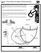
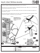
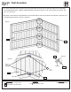
A: Use (281) TNR Upright as a guide to judge the proper bolt location, remove the bottom pan bolt and nut. The
bolt will no longer be needed, but keep the lock nut. (g. 30.1 and 30.2)
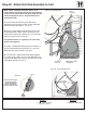
B: Attach the top of the TNR3 Post Mount to TNR2 Slide Clamp Ring using 1 (PB2) 1/4 x 1-1/4” Pan Bolt (with
the previously removed lock nut). (g. 30.2)
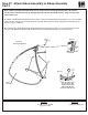
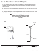
C: Insert TNR3 Post Mount on (281) TNR Upright, pre-drill with a 1/8” drill bit then attach with 2 (S6) #12 x 1”
Pan Screws. (g. 30.3)
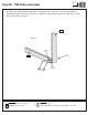
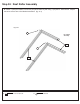
D: Attach (280) TNR Ground Brace ush to the bottom of (041) Narrow Back Panel with 2 (S11) #8 x 2” Wood
Screws and 1 (S4) #8 x 3” Wood Screw. (g. 30.1 and 30.4)
TNR3 Post
Mount
Remove PB1 (1/4 x 3/4”
PanBolt)rsttheninstall
PB2 (1/4 x 1-1/4” Pan Bolt
with previously removed
lock nut)
Fig. 30.1 Fig. 30.2
PB2
281
281
Lock
Nut
S6
Fig. 30.3
S4
280
S11
S11
S4
S6
041
041
280
Fig. 30.4
TNR3 Post
Mount
75 support@cedarsummitplay.com