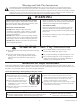
B A N C R O F T P L AY H O U S E – P 2 8 0 0 8 0 INSTALLATION AND OPERATING INSTRUCTIONS WARNING 4'-8 1/4" To reduce the risk of serious injury or death, you must read and follow these instructions. Keep and refer to these instructions often and give them to any future owner of this playhouse. Manufacturer contact information provided below. CAPACITY - 3 Users Maximum, Ages 2 to 10. 4'-4 5/8" RESIDENTIAL HOME USE ONLY.
Warnings and Safe Play Instructions CONTINUOUS ADULT SUPERVISION REQUIRED. Most serious injuries and deaths on playground equipment have occurred while children were unsupervised! Our products are designed to meet mandatory and voluntary safety standards. Complying with all warnings and recommendations in these instructions will reduce the risk of serious or fatal injury to children using this play system.
Keys to Assembly Success Tools Required • Tape Measure • Carpenters Level • Carpenters Square • Claw Hammer • Standard or Cordless Drill • #1 & #2 Phillips or Robertson bits • Ratchet with extension (7/16” sockets) Part Identification Key On each page, you will find the parts and quantities required to complete the assembly step illustrated on that page. Here is a sample.
About Our Wood Cedar Summit Premium Play Systems uses only premium playset lumber, ensuring the safest product for your children’s use. Although we take great care in selecting the best quality lumber available, wood is still a product of nature and susceptible to weathering which can change the appearance of your set.
Your Key To Quick Assembly SORTING WOOD PARTS INTO EACH ASSEMBLY STEP WILL SAVE TIME! Step Step Step SAVE TIME - TIP #1: Open box with wood parts and look for the Key Number stamped on the end of the wood part (see chart below). Sort each wood part into the different assembly steps. 1X 1316 131 Cafe Top FSC 15.9 x 127 x 1225.
5/16" (8mm) Flat Washer 1/4" (6mm) Lock Washer 5/16" (8mm) T-Nut 1/4" (6mm) T-Nut 1/4" (6mm) Flat Washer 5/16" (8mm) Flat Washer For example: BOLT LENGTH 4½ (4.5) inches long 1 inch = 25.4mm LENGTH CONVERSION 0.31 inches x 25.4mm = 8mm BOLT DIAMETER 5/16 (0.31) inches For example: 1 inch = 25.4mm DIAMETER CONVERSION HARDWARE LENGTH CHART inches vs millimetres 6 152 5½ 140 5 127 114 4½ 4 102 3½ 89 3 76 2½ 64 2 51 1½ 38 1¼ 32 1-1/8 29 1 25.4 7/8 22 3/4 19 1/2 12.
63.5 2 1/2" 5/4 x 3 88.9 3 1/2" 5/4 x 4 114.3 4 1/2" 5/4 x 5 139.7 5 1/2" 5/4 x 6 88.9 3 1/2" 4x4 38.1 1 1/2" 34.9 1 3/8" 34.9 1 3/8" 38.1 1 1/2" 38.1 1 1/2" 2x6 136.5 5 3/8" 2x4 85.7 3 3/8" 2x3 63.5 2 1/2" 2 x2 15.9 5/8" 82.6 3 1/4" 34.9 1 3/8" 60.3 2 3/8" 85.7 3 3/8" 114.3 4 1/2" 136.5 5 3/8" 1/2 x 4 1x2 1x3 1x4 1x5 1x6 LENGTH CONVERSION 1 inch = 25.4mm 59.25 inches x 25.4mm = 1505mm For example: BOARD LENGTH 59¼ (59.25) inches 15.9 5/8" 15.9 5/8" 15.9 5/8" 15.
Part Identification (Reduced Part Size) 2pc. - 0336 - 10 x 25.4 x 413.8 - Window Trim - 38033636 (3/8 x 1 x 16‐5/16") 2pc. - 0375 - 11.9 x 76.2 x 533.7 - Cafe Side - 38037536 (7/16 x 3 x 21") 1pc. - 0373 - 11.9 x 76.2 x 556 - Chalkwall Side - 38037336 (7/16 x 3 x 21‐7/8") 1pc. - 0377 - 11.9 x 127 x 1225.6 - Cafe Top - 38037736 (7/16 x 5 x 48‐1/4") 4pc. - 0376 - 12.7 x 108 x 665.0 - Soffit Wide - 38037636 (1/2 x 4‐1/4 x 26‐3/16") 1pc. - 0333 - 15.9 x 22.2 x 330.
Part Identification (Reduced Part Size) 1pc. - 0317 - 15.9 x 108 x 958.9 - Long Cafe Gable - 3 8031736 (5/8 x 4‐1/4 x 37‐3/4") 1pc. - 0312 - 15.9 x 108 x 1168.4 - Gable Block Long - 3 8031236 (5/8 x 4‐1/4 x 46") 8pc. - 0318 - 15.9 x 38.1 x 152.4 - Tie Block - 38031836 (5/8 x 1‐1/2 x 6") 1pc. - 0313 - 23.8 x 38.1 x 549.3 - Roof Gable Support - 38031336 (15/16 x 1‐1/2 x 21‐5/8") 1pc. - 0319 - 23.8 x 63.5 x 127 - Door Latch Block - 38031936 (15/16 x 2‐1/2 x 5") 1pc. - 0390 - 23.8 x 108 x 762.
Part Identification (Reduced Part Size) 1pc. - 0345 - 36.5 x 63.5 x 206.5 - Window Arch Assy (Green) - 38034501 (1‐7/16 x 2‐1/2 x 8‐1/8") 2pc. - 0393 - 28.6 x 190 x 419.1 - Shutter Assy (Green) - 38039301 (1‐1/8 x 7‐1/2 x 16‐1/2") 1pc. - 0335 - 27.8 x 571.5 x 1073.2 - Half Wall Panel - 38033536 (1‐1/8 x 22‐1/2 x 42‐1/4") 1pc. - 0322 - 27.8 x 381 x 990.6 - Front Left Wall - 38032236 (1‐1/8 x 15 x 38‐7/8") (1‐1/4 x 16‐9/16 x 40") 1pc. - 0329 - 31.8 x 420.7 x 1015.
Part Identification (Reduced Part Size) 1pc. - 0324 - 27.8 x 1016 x 1073.2 - Shutter Wall Panel - 38032436 (1‐1/8 x 40 x 42‐1/4") 1pc. - 0325 - 27.8 x 1016 x 1214.4 - Back Wall Panel - 38032536 11 (1‐1/8 x 40 x 47‐13/16") support@solowavedesign.
Part Identification (Reduced Part Size) 1pc. - 0320 - 33.7 x 920.5 x 1270 - Back Roof Panel - 38032036 (1‐5/16 x 36‐1/4 x 50") 1pc. - 0321 - 33.7 x 926.9 x 1270 - Front Roof Panel - 38032136 (1‐5/16 x 36‐1/2 x 50") 12 support@solowavedesign.
Hardware Identification (Actual Size) 8pc. S3 - Wood Screw #8 x 2-1/2" - (52045522) 16pc. S15 - Wood Screw #8 x 1-3/4" - (52045513) 92pc. S2 - Wood Screw #8 x 1-1/2" - (52045512) 9pc. TS - Trim Screw #6 x 30mm - (52955911) 8pc. S18 - Wood Screw #6 x 1" - (52015910) 70pc. S26 - Pan Screw #8 x 2" - (52445520) 76pc. S13 - Pan Screw #6 x 5/8" - (9264990) 17pc. S0 - Truss Screw #8 x 7/8" - (52935505) 2pc. S10 - Pan Screw #8 x 1" - (52435510) 1pc.
Part Identification (Reduced Part Size) 1x - Flower Box Set (Green)(2Pk) (3320402) 1x - Shutter Pivot w.
Step 1: Inventory Parts - Read This Before Starting Assembly STOP A. STOP STOP STOP his is the time for you to inventory all your hardware, wood and accessories, T referencing the parts identification sheets. This will assist you with your assembly. • The wood pieces will have the four digit key number stamped on the ends of the boards. The wood pieces are referenced throughout the instructions with this number. • Please refer to Page 6 for proper hardware assembly.
Step 2: Shutter Assembly A: Place 1 Door Handle on each (0393) Shutter Assembly centred over 1 panel as shown in fig. 2.1. Attach with 2 (S13) #6 x 5/8” Pan Screws per handle. B: On the opposite side as the Door Handles attach 2 Shutter Pivots to each (0393) Shutter Assembly using provided hardware, as shown in fig. 2.1. Shutter Pivot with Hardware Fig. 2.
Step 3: Roof Assembly Part 1 A: Attach 1 (0316) Roof Side to another flush at the peak using 2 (S3) #8 x 2-1/2” Wood Screws. Do this twice so you have 2 Roof Support Assemblies. (fig. 3.1) Fig. 3.1 S3 0316 Wood Parts 4x 0316 Roof Side 1-3/16 x 3-1/4 x 35-7/8” Hardware 4x S3 #8 x 2-1/2” Wood Screw 17 support@solowavedesign.
Step 3: Roof Assembly Part 2 B: Place (0320) Back Roof Panel and (0321) Front Roof Panel on each of the Roof Support Assemblies so the Joist Sides of the Roof Panels are flush to the bottoms of each (0316) Roof Side. (fig. 3.2 and 3.3) The (0321) Front Roof Panel must overlap the (0320) Back Roof Panel and connect tightly. (fig. 3.4) C: Attach each Roof Support Assembly to the Roof Panels with 6 (S26) #8 x 2” Pan Screws per side. (fig. 3.2) Fig. 3.4 0320 0321 Fig. 3.2 0320 0316 0321 0316 Fig. 3.
Step 3: Roof Assembly Part 3 D: From underneath the Roof Assembly centre 1 Corner Bracket on each Joist and attach with 3 (S13) #6 x 5/8” Pan Screws per bracket as shown in fig. 3.5 and 3.6. View from Underneath Fig. 3.5 Joist centred Corner Bracket Fig. 3.6 S13 x 3 per bracket Other Parts Hardware 9x S13 #6 x 5/8” Pan Screw 19 3 x Corner Bracket support@solowavedesign.
Step 3: Roof Assembly Part 4 E: Tight to the Roof Panels attach 1 (0330) Top Roof Side Left and 1 (0337) Top Roof Side Right to each Roof Support Assembly with 4 (S2) #8 x 1-1/2” Wood Screws per board so the peaks are tight and the bottom of each board is flush to the bottom of each Roof Panel. Notice the pilot holes are towards the Roof Panel. (fig. 3.7) Fig. 3.7 0330 (hidden) Notice holes towards panel.
Step 4: Front Wall Assembly A: Place (0372) Top Front Panel on top of (0322) Front Left Wall and (0323) Front Right Wall so the ends are flush. Attach from the opening in the Front Left and Right Walls with 2 (S26) #8 x 2” Pan Screws. (fig. 4.1) B: Place (0371) Front Bottom to the bottom of (0322) Front Left Wall and (0323) Front Right Wall so the ends are flush with the outside edge of each Wall and attach with 4 (S15) #8 x 1-3/4” Wood Screws.
Step 5: Window Wall Assembly A: Place (0324) Shutter Wall Panel tight to (0369) Corner Trim on (0322) Front Left Wall so the inside board is flush to the inside edge of (0369) Corner Trim. Attach (0369) Corner Trim to (0324) Shutter Wall Panel with 5 (S26) #8 x 2” Pan Screws. (fig. 5.1) B: Place (0374) Top Side Panel on top of (0324) Shutter Wall Panel so the inside edges are flush. Notice the middle pilot holes are towards the bottom of the board.
Step 6: Back Wall Assembly A: Place (0325) Back Wall Panel tight to (0369) Corner Trim on (0324) Shutter Wall Panel so the inside board is flush to the inside edge of (0369) Corner Trim. Attach (0369) Corner Trim to (0325) Back Wall Panel with 5 (S26) #8 x 2” Pan Screws. (fig. 6.1) B: Place (0370) Top Back Panel on top of (0325) Back Wall Panel so the inside edges are flush. Attach (0369) Corner Trim to (0370) Top Back Panel with 2 (S26) #8 x 2” Pan Screws. (fig. 6.
Step 7: Half Wall Assembly A: Place (0335) Half Wall Panel between (0323) Front Right Wall and (0325) Back Wall Panel so the inside edges are flush to the inside edges of both (0369) Corner Trims. Attach (0335) Half Wall Panel to both (0369) Corner Trims with 3 (S26) #8 x 2” Pan Screws per side. (fig. 7.1) B: Maintain measurement of 47-13/16” between the inside of the Half Wall and Window Wall. (fig. 7.1) Window Wall Fig. 7.
Step 8: Soffit Assembly A: Mark the centre point of both (0372) Top Front Panel and (0370) Top Back Panel. (fig. 8.1) B: Place 2 (0376) Soffit Wides tight together on top of (0372) Top Front Panel so the inside edges line up with the marked out spot from Step A. Use the pilot holes that are towards the inside of the assembly. Remaining holes will be used in the next step. Attach (0376) Soffit Wides to (0372) Top Front Panel and both (0369) Corner Trims with 4 (S2) #8 x 1-1/2” Wood Screws per board. (fig. 8.
Step 9: Attach Roof to Assembly Make sure assembly is square before proceeding in this Step. A: With an adult helper lift the Roof Assembly from Step 3 onto the (0376) Soffit Wides so the tips of the (0316) Roof Sides are flush to the ends of each (0376) Soffit Wide. (fig. 9.1 and 9.2) B: Attach (0376) Soffit Wides to Roof Assembly with 3 (S2) #8 x 1-1/2” Wood Screws per soffit. Make sure screws go into each (0316) Roof Side and the outside Joists in the Roof Assembly. (fig. 9.1 and 9.3) Fig. 9.
Step 10: Attach Cafe Top A: On the Half Wall Side place (0377) Cafe Top tight to top of (0376) Soffit Wides and attach to (0316) Roof Sides with 4 (S2) #8 x 1-1/2” Wood Screws. (fig. 10.1) 0316 Fig. 10.1 Note: Orientation of board. Parts removed for clarity. 0377 0316 (hidden) 0376 S2 Tight 0376 Half Wall Inside view Wood Parts 1x 0377 Cafe Top 7/16 x 5 x 48-1/4” Hardware 4x S2 #8 x 1-1/2” Wood Screw 27 support@solowavedesign.
Step 11: Cafe Gable Assembly Part 1 A: From inside the assembly place (0317) Long Cafe Gable tight to top of (0377) Cafe Top with arch facing up then attach to (0316) Roof Sides with 4 (S2) #8 x 1-1/2” Wood Screws. (fig. 11.1 and 11.2) B: Measure 2-3/4” up from (0317) Long Cafe Gable and place (0314) Short Cafe Gable against the (0316) Roof Sides with arch facing down and tight to the Roof Panels then attach with 4 (S2) #8 x 1-1/2” Wood Screws. (fig. 11.1 and 11.2) Tight Fig. 11.
Step 11: Upper Half Wall Assembly Part 2 C: From inside the assembly place 3 (0315) Chalkwall Supports as shown in fig. 11.3, making sure the notched out ends fit around the supports on the inside of (0335) Half Wall Panel. The distance between the 2 closest boards should be maintained at 9-1/4”. (fig. 11.3 and 11.4) D: From the outside of the assembly attach the two outside (0315) Chalkwall Supports to (0377) Cafe Top and (0335) Half Wall Panel with 2 (S0) #8 x 7/8” Truss Screws per board. (fig. 11.
Step 12: Window Wall Gable Assembly Part 1 A: Place Small Gable Vent between the 2 (0316) Roof Sides on the Window Wall tight to the peak. From inside the assembly attach Small Gable Vent to (0316) Roof Sides with 4 (S13) #6 x 5/8” Pan Screws. (fig. 12.1 and 12.2) Note 6 screws are shown in fig. 12.2, but only 4 are used. The remaining 2 will be used in the next step. Fig. 12.1 0316 Window Wall Fig. 12.2 Tight 0316 Small Gable Vent S13 x 4 0316 Note: These 2 screws shown for reference only.
Step 12: Window Wall Gable Assembly Part 2 B: Tight to both (0316) Roof Sides place (0313) Roof Gable Support and attach to both (0316) Roof Sides with 2 (S2) #8 x 1-1/2” Wood Screws. (fig 12.3 and 12.4) C: From inside the assembly attach Small Gable Vent to (0313) Roof Gable Support with 2 (S13) #6 x 5/8 Pan Screws. (fig. 12.5) Small Gable Vent Fig. 12.4 0313 0316 Tight 0316 Fig. 12.3 S2 Small Gable Vent 0316 Fig. 12.
Step 12: Window Wall Gable Assembly Part 3 D: Tight to the top of (0374) Top Side Panel place (0312) Gable Block Long and attach to both (0316) Roof Sides with 4 (S2) #8 x 1-1/2” Wood Screws. (fig 12.6) E: Tight to the top of (0312) Gable Block Long place (0378) Gable Block and attach to both (0316) Roof Sides with 4 (S2) #8 x 1-1/2” Wood Screws. (fig 12.6) F: Tight to the top of (0378) Gable Block place (0379) Gable Block Short and attach to both (0316) Roof Sides with 4 (S2) #8 x 1-1/2” Wood Screws.
Step 13: Window Wall Shutter Assembly Part 1 A: Centre (0397) Shutter Top over opening in (0324) Shutter Wall Panel, flush to the bottom of (0374) Top Side Panel, then place (0345) Window Arch Assembly centred on top of (0397) Shutter Top. (fig. 13.1 and 13.2) B: From inside the assembly attach (0374) Top Side Panel to (0345) Window Arch Assembly and (0324) Shutter Wall Panel to (0397) Shutter Top with 4 (S15) #8 x 1-3/4” Wood Screws. (fig. 13.3 and 13.4) Fig. 13.1 Fig. 13.
Step 13: Window Wall Shutter Assembly Part 2 C: Insert the bottom Shutter Pivots in the 2 (0393) Shutter Assemblies from Step 2 into (0396) Shutter Bottom. (fig. 13.5 and 13.6) D: Tilt assembly and lift up to insert top Shutter Pivots into (0397) Shutter Top. Make sure it is snug. (fig. 13.6 and 13.7) E: Make sure (0396) Shutter Bottom is square to (0397) Shutter Top then from inside the assembly attach (0396) Shutter Bottom to (0324) Shutter Wall Panel with 2 (S15) #8 x 1-3/4” Wood Screws. (fig 13.8) Fig.
Step 13: Window Wall Shutter Assembly Part 3 F: Attach 1 (0336) Window Trim to each side of the opening in (0324) Shutter Wall Panel using 3 (TS) #6 x 30 mm Trim Screws per board. Notice the pilot holes are towards the inside of the assembly. (fig. 13.9 and 13.10) G: Place (0333) Shutter Stop tight to top of (0396) Shutter Bottom and tight to the panel then attach to (0396) Shutter Bottom using 3 (TS) #6 x 30 mm Trim Screws. (fig. 13.10) Fig. 13.9 Fig. 13.
Step 13: Window Wall Shutter Assembly Part 4 H: Attach 4 (0318) Tie Blocks flush to top of (0370) Top Back Panel and to (0325) Back Wall Panel in the places shown in fig. 13.11 using 2 (S2) #8 x 1-1/2” Wood Screws per (0318) Tie Block. I: Attach 2 (0318) Tie Blocks flush to top of (0374) Top Side Panel and to (0324) Shutter Wall Panel in the places shown in fig. 13.11 using 2 (S2) #8 x 1-1/2” Wood Screws per (0318) Tie Block.
Step 14: Door Assembly Part 1 A: On the outside of (0329) Door Panel attach 2 Door Hinges using 3 (S13) # 6 x 5/8” Pan Screws per Hinge. Judge spacing based on fig. 14.1. B: On the outside of (0329) Door Panel attach 1 Door Handle as shown in fig. 14.1, using 2 (S13) #6 x 5/8” Pan Screws. C: On the inside of (0329) Door Panel attach a second Door Handle at the same spot as the one on the outside. Use 2 (S13) #6 x 5/8” Wood Screws. (fig. 14.1 and 14.
Step 14: Door Assembly Part 2 E: In the opening for the door on the Front Wall, measure 5/8” up from the top of (0371) Front Bottom then attach remaining side of the Door Hinges on (0329) Door Panel to (0322) Front Left Wall with 3 (S13) #6 x 5/8” Pan Screws per hinge. (fig. 14.3 and 14.4) Fig. 14.3 0322 Front Wall 0371 Fig. 14.4 S13 0329 5/8” 0322 0371 Hardware 6x S13 #6 x 5/8” Pan Screw 38 support@solowavedesign.
Step 14: Door Assembly Part 3 F: In the notched out opening of (0319) Door Latch Block attach the Magnetic Catch using 2 (S18) #6 x 1” Wood Screws. (fig. 14.5) Important: Use a hand held screw driver and DO NOT over tighten. G: From inside the assembly measure 15-1/8” up from the bottom of (0371) Front Bottom on the (0323) Front Right Wall and place (0319) Door Latch Block so it overhangs and the Catch Plate can connect to the Magnetic Catch. Attach with 2 (S15) #8 x 1-3/4” Wood Screws. (fig. 14.5 and 14.
Step 15: Attach Windows A: Place 1 Playhouse Window in each window opening on the Front and Back Walls as well as in the (0329) Door Panel. There should be 5 Playhouse Windows in total. Attach with 4 (S13) #6 x 5/8” Pan Screws per Playhouse Window. (fig. 15.1 and 15.2) Fig. 15.1 Back Wall Fig. 15.2 0329 Front Wall Playhouse Window x 5 S13 x 4 per window Hardware 20 x S13 #6 x 5/8” Pan Screw 40 Other Parts 5 x Playhouse Window support@solowavedesign.
Step 16: Attach Flower Boxes A: Place 1 Flower Box under each window opening on (0322) Front Left Wall and (0323) Front Right Wall and attach with 2 (S13) #6 x 5/8” Pan Screws per Flower Box. (fig. 16.1 and 16.2) Fig. 16.1 0322 Fig. 16.2 0323 S13 Flower Box Hardware 4x S13 #6 x 5/8” Pan Screw 41 Other Parts 2 x Flower Box support@solowavedesign.
Step 17: Cafe Gable Assembly Part 1 A: From outside of the assembly place 1 (0332) Cafe Roof flush to the inside edge of (0316) Roof Side with the angled edge at the top. Top of board should align with the peak of the Roof Assembly. Attach (0332) Cafe Roof to (0316) Roof Side with 3 (S2) #8 x 1-1/2” Wood Screws. (fig. 17.1, 17.2 and 17.3) B: Place a second (0332) Cafe Roof flush to the inside edge of (0316) Roof Side on the other side,angled edge at the top.
Step 17: Upper Half Wall Assembly Part 2 D: Place (0390) Cafe Table Top between 2 (0315) Chalkwall Supports so the grooves are tight to each support as shown in fig. 17.5 and 17.6. Attach with 2 (S3) #8 x 2-1/2” Wood Screws per (0315) Chalkwall Support. E: On the outside of the assembly centre (0620) SL Brace on the underside of (0390) Cafe Table Top so it lines up with the pilot holes on (0335) Half Wall Panel.
Step 17: Upper Half Wall Assembly Part 3 F: From outside of the assembly place 2 (0375) Cafe Sides over the 2 (0315) Chalkwall Supports that surround the (0390) Cafe Table Top so the edges are flush to each other. Each (0375) Cafe Side should fit tight to both (0377) Cafe Top and (0390) Cafe Table Top. Attach with 3 (S0) #8 x 7/8” Truss Screws per board. (fig. 17.8) G: From outside the assembly place (0373) Chalkwall Side on the remaining (0315) Chalkwall Support so the inside edges are flush.
Step 18: Cafe Gable Assembly A: Insert Roof Peak Spinner into slot of Roof Peak Mount. (fig. 18.1) B: Place Roof Peak Mount in opening above (0314) Short Cafe Gable tight to the peak and flush to the bottom of (0314) Short Cafe Gable. From outside the assembly attach Roof Peak Mount to (0332) Cafe Roofs with 4 (S13) #6 x 5/8” Pan Screws. (fig. 18.1 and 18.2) Fig. 18.1 Tight Fig. 18.
Step 19: Attach Spin Chalk Sign Part 1 A: Place (0366) Spin Trim Bottom on (0335) Half Wall Panel, between both (0315) Chalkwall Supports, so the arches are flush then attach with 2 (S18) #6 x 1” Wood Screws. (fig. 19.1 and 19.2) B: Place (0367) Spin Trim Top on (0377) Cafe Top, between both (0315) Chalkwall Supports, so the arches are flush then attach with 2 (S18) #6 x 1” Wood Screws. (fig. 19.1 and 19.2) Fig. 19.1 Fig. 19.2 Parts removed for clarity.
Step 19: Attach Spin Chalk Sign Part 2 C: Place Spin Chalk Sign between (0315) Chalkwall Supports and attach with 6 (S13) #6 x 5/8” Pan Screws. (fig. 19.3, 19.4 and 19.5) Fig. 19.3 Spin Chalk Sign Fig. 19.4 Parts removed for clarity. 0315 Outside View Fig. 19.5 0315 S13 x6 Inside View Spin Chalk Sign Hardware 6x S13 #6 x 5/8” Pan Screw 47 Wood Parts 1 x Spin Chalk Sign support@solowavedesign.
Step 20: Attach Door Bell Assembly Note: Install 2 AA Batteries in Doorbell prior to attaching to assembly. A: On the outside of the assembly attach Doorbell Trim to (0323) Front Right Wall, in the hole provided with 2 (S13) #6 x 5/8” Pan Screws, as shown in fig. 20.1 and 20.2. B: From inside the assembly attach Doorbell to (0323) Front Right Wall with 2 (S10) #8 x 1” Pan Screws. (fig. 20.1 and 20.3) Fig. 20.1 0323 Fig. 20.3 Inside View Fig. 20.
Step 21: Attach Playhouse Plaque A: From outside the Playhouse attach Playhouse Plaque to (0316) Roof Sides with 2 (S13) #6 x 5/8” Pan Screws as shown in fig. 21.1 and 21.2 0316 Fig. 21.1 Outside View 0316 Playhouse Plaque Fig. 21.2 S13 Outside View Hardware 2x S13 #6 x 5/8” Pan Screw 49 Other Parts 1 x Playhouse Plaque support@solowavedesign.
NOTES 50 support@solowavedesign.
NOTES 51 support@solowavedesign.
CEDAR SUMMIT Consumer Registration Card First Name Initial Last Name Street Apt. No.