
K Series Installation Manual

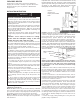


Minimum Clearances
Heater to Floor: heater may be mounted directly on fi nished
foor or, if desired, above fl oor (such as above the baseboard).
Up to 3/4 inch (19 mm) of carpeting may be installed up to and
around heater as long as it does not obstruct the air fl ow.
Heater to Drapery: do not install heater where curtains or
drapery will contact the heater. See Figure 2 for required mini-
mum clearances.
Furniture: maintain at least 6 inches (152 mm) space between
furniture and heater to allow for proper air fl ow.
UNPACKING HEATER
Check heater to make sure it has not been damaged in
shipping. Do not install or attempt to operate the heater if
damaged. Return to place of purchase or fi le claim with
freight carrier.
INSTALLATION INSTRUCTIONS
1. Serious injury or death could result from electric shock.
Make sure electrical power supply circuit coming to heater
is disconnected at main disconnect or service panel before
installing this heater.
2. Wiring procedures and connections must be in accordance
with the National Electrical Code (NEC) and local codes.
Refer to Wiring Diagrams Figure 5. Make sure all electrical
connections are tight to prevent possible overheating. Use
Copper Supply Wire Only.
3. Verify the electrical power supply voltage matches the
voltage rating as printed on the heater nameplate – see Fig-
ure 1.
TO REDUCE THE RISK OF FIRE AND ELECTRIC SHOCK
OR INJURY TO PERSONS, OBSERVE THE FOLLOWING:
CAUTION - Never connect a heater to a voltage
greater than the nameplate voltage as this will
damage the heater and could cause a fi re.
4. Do not install the heater against combustible low-den-
sity cellulose fi berboard surfaces, against or below vinyl wall
coverings, or below any materials that may be damaged by
heat such as vinyl or plastic blinds, curtains, etc.
5. Do not install heater below an electrical convenience re-
ceptacle (outlet).
6. CAUTION – Heater Operates at High Temperatures. Keep
Electrical Cords (including telephone and computer cables),
Drapes, and Other Furnishings Away From Heater. For effi -
cient and safe operation, we recommend maintaining a mini-
mum of 6 inches (152 mm) clearance above and in front of
the heater at all times. See Figure 2 for minimum clearance
requirements for drapery.
7. To reduce the risk of fi re, do not store or use gasoline
or other fl ammable vapors or liquids in the vicinity of the
heater.
8. Do not install heater upside down or in any position other
than as shown in this manual. Caution label with word “TOP”
must be at the top when heater is installed.
9. Do not recess heater in wall or install heater inside any
type enclosure as this will cause heater to overheat and
could create a hazard.
10. When mounting heater, (see Figure 4), make sure screws
do not damage crossover wiring or the safety limit in the
heater.
11. Do not remove or bypass the safety limit control as this
could allow heater to become a fi re hazard – see Figure 4.
12. When using Transformer Relay Accessory, supply wiring
provided in compartment where this accessory is installed,
must be rated 90 °C minimum.
Important Note: Certain fabrics and materials discolor or may
become damaged by heat. Therefore, avoid installing heater
against vinyl wall coverings or below plastic or vinyl items such
as blinds or vinyl drapes since these items may become
damaged by the heated air flowing from the heater.
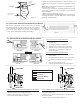
1. Remove wiring compartment cover at end of heater where
power supply cable is to enter (Figure 3). Determine desired
mounting location, position heater to wall and mark wall
(or fl oor) at location where power supply is to enter heater.
2. The air inlet of the heater cannot be obstructed by the
finished floor materials such as carpet, tile or hardwood. The
installer, must make allowance for the finished floor materials
when installing the heater during rough-in construction on a
subfloor. For example if thickness of the padding and carpet
to be installed is 3/4", then the heater must be mounted 3/4"
above the subfloor.
Figure 3
Wiring compartment
cover
Front Cover
Screw
NOTE: For most effi
cient operation locate heaters along out-
side wall under windows. Position heater so it can be secured
to wall stud. Power cable must enter heater through built
in cable clamp or one of the knockouts provided in wiring
compartment.
Figure 2:
Clearance for
Drapery and Finished
Floor
2. Drill hole in wall (or fl oor) at desired location for power sup-
ply entry. Install power supply wiring to heater and thermostat
location as determined by thermostat option selected. Allow
approximately 10 to 12 in (254mm to 305mm) of wire at heater
for connections.
3. If any accessories are to be used with this heater, refer to
installation instructions provided with the accessory for proper
installation and wiring. Visit www.king-electric.com for instruc-
tions on some common accessories.
4. Position heater at desired location and attach to wall using
good screws or appropriate hardware. Locate studs and drive
screws into studs where possible. For heaters up to 6 feet (1.8
m) in length, one screw at each end is adequate. For longer
units, an additional screw in center is required. Tighten screws
and then loosen screws at least ¼ turn to allow heater to ex-
pand and contract during use. If unit is mounted above fl oor,
two additional mounting holes are provided at each end below
the heating element (see Figure 4). Install an additional screw
at each end for stability making sure to loosen each screw at
least ¼ turn.
5. Connect the supply cable grounding wire to the green wire
pigtail in wiring compartment.
WARNING