FPC-02 Series Installation and Operating manual
Index Introduction…………………………………………………………………...……. 3 FPC-02 Installation notes ……...…………...…………………………………... 4 Wiring the FPC-02-120V, FPC-02-120V-MDB ………………………………. 5 Wiring the FPC-02-240V, FPC-02-240V-MDB ………………………………. 6 Operating instructions……………………………………………………………. 7 Turning the system ON and OFF………………………………………………. 7 Selecting temperature scale…………………………………………………….. 7 Selecting Automatic or Manual mode …………………………………………. 7 Heater indication…………..……………………………………………………...
Introduction The FPC-02 Series power boxes offer smart and easy control for HEAT TRACING SYSTEMS. It can operate one heating zones. Typical applications include pipes, valves and gutters. The backlit LCD screen provides full interface and information to the system status.
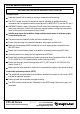
FPC-02 Series Installation PLEASE READ THIS MANUAL AND THE SAFETY WARNINGS CAREFULLY BEFORE INSTALLING AND USING THE CONTROLLER AND SAVE IT FOR FUTURE USE Installation notes Familiarize yourself with the markings, warnings, components and terminology. The FPC-02 power boxes and its accessories must be installed by a qualified electrician in accordance with local regulations and the requirements of the NEC (NFPA 72 ) and the CEC part 1.
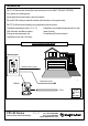
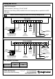
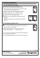
Wiring the FPC-02 Heater load connection Provide terminals L, N with up to 120 VAC, 30 AMP. Make sure the wire Gauge (AWG) is suitable for the circuit Amperage draw, as specified in the NEC/ CEC table 1. Caution: Incorrect voltage may cause fire or seriously damage the unit. FPC-02-120V N N L L NO NC HE C C 1 2 GFEP Main Supply 120 VAC Indication Dry Contact (NO/NC) *See table Heater Load connection 120 VAC, 30A Branch circuit protection and disconnect provided by installer. Max.
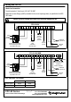
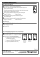
Wiring the FPC-02 Heater load connection Provide terminals L, N with up to 240 VAC, 30 AMP. Make sure the wire Gauge (AWG) is suitable for the circuit Amperage draw, as specified in the NEC/ CEC table 1. Caution: Incorrect voltage may cause fire or seriously damage the unit. FPC-02-240V L1 L1 L2 L2 NO NC HE C C 1 2 GFEP Main Supply 240 VAC Indication Dry Contact (NO/NC) *See table Heater Load connection 240 VAC, 30A Branch circuit protection and disconnect provided by installer. Max.
Operating instructions Turning the system ON and OFF Press and hold the [ON] button for 0.5 seconds to turn the system ON or OFF. The words “ON” or “OFF” will appear on display. When ON, the green LED on the front panel will also turn ON . Selecting temperature scale Press the [+] button for Celsius. Press the [-] button for Fahrenheit.
Technician settings Use the technician settings mode to view and adjust the following parameters: P01 P02 P03 P04 P05 Temperature set point Lower ambient temperature limit to stop the heater Time delay before stopping the heater ON time for manual mode Not in use Enable/Disable 2nd temperature sensor logic (Aquastat) P07 Not in use P08 MODBUS MAC Address for home automation system (option) P09 Commissioning / Test mode Restore defaults P06 Enter technician settings mode Disconnect power and open the int
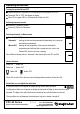
Technician settings (Cont’) P02 - Lower limit temperature for heating Press the [SELECT] and [+] buttons simultaneously. “P02” and the low limit temperature will appear on display. When the temperature on the temperature sensor drops below the low temperature limit, the heating system will stop. Use the [+] and [-] buttons to adjust the temperature set point. Range: -40…+23°F / -40…-5°C Default: -40°F / -40°C Press the [SELECT] and [+] buttons simultaneously again.
Technician settings (Cont’) P04 - Manual mode ON time Press the [SELECT] and [+] buttons simultaneously. “P04”, “On” and the time “Manual ON” mode time period will appear on display. The hours will blink. The delay time parameter defines a time frame in which the heater remains ON after receiving an “Manual ON” command. Use the [+] and [-] buttons to adjust the hours of the working time. Range: 00...99 hours Default: 03 hours Manual ON (minutes) Press the [SELECT] and [+] buttons simultaneously again.
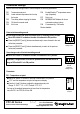
Technician settings (Cont’) P07 – Not in use Press the [SELECT] and [+] buttons simultaneously. “P07” will appear on display. Proceed to P08. P08 – MODBUS MAC Address (for MDB models only) Press the [SELECT] and [+] buttons simultaneously. “P08” and the MODBUS MAC Address will appear on display. Use the [+] and [-] buttons to set the MAC Address of the unit. Setting the MAC address for the unit will make it available through the home automation system. Range: 0 – 60.
Technician settings (Cont’) P09 - Test conditions mode / Technician commissioning mode Turn ON test conditions to check the functionality of the system regardless of temperature sensors parameters (i.e. during the summer). In test conditions, the Ambient temperature is always -7°C/19°F. Press the [SELECT] and [+] buttons simultaneously. “P09” will appear on display. The hours will blink. Use the [+] button to enter test/commissioning mode – the word “Test” will appear on display.
Technician settings (Cont’) DIP switch S2 - Short measuring times (test only) Use DIP switch S2 to short the - “ON” - Short measuring times – for test/commissioning only (measuring times will be divided by 60). - “OFF” - Normal operation. Short measuring times: A real 1 hour will take 1 minute and a real 1 minute will take 1 second. DIP switches S3 and S4 – Not in use (must be in OFF position) S3 OFF, FPC-02 Series S4 OFF Owner’s manual & Technician Settings Pg.
System Errors Error 1 – MODBUS Communication error “Aux1” Will appear on display. Communication error Error 2 – Temperature sensor is not connected or short circuit “SensErr 1” Will appear on display. Temperature Sensor error GFEP The GFEP is designed to provide protection for electrical equipment. GFEP TEST The GFEP should be tested monthly. Press the blue “T” test button to trip the outlet and break the circuit. The YELLOW LED on the front panel should lit.
Object list (for MDB models only) OBJECT LIST FOR FPC-02-MDB Series rev. 1.0 MODBUS RTU Mode, Address Slave 1-60, Baud Rate 9600, n, 8, 1 All Registers Signed Integer 16 bit, R - Register Read Only, R/W - Register Read/Write Dec,[Hex] Value Description Read/Write 0, [0000] -13°F .. 54°F/ -40..+16°C Measured Temperature R 1, [0001] 5°F... 59°F /-15°C...+15°C P01 – Temperature set point R/W 2, [0002] -40°F... +23°F/-40°C...
Tel: (856) 2882882 Tel: +972-3-9626462 Fax: +972-3-9626620 support@meitavtec.com www.meitavtec.