
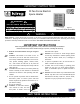
Use and Care Manual


ELECTRIC SHOCK OR FIRE HAZARD
!
!
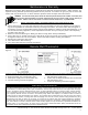
Figure 3
2
W INSTALLATION INSTRUCTIONS
CAUTION!
Turn OFF all electrical power
to install heater
Rating Label Location
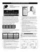
Total Amps
Minimum AWG. Wire
Size (Copper
Circuit Breaker or
Fuse Size
0 thru 12 #14 15 amp
12.1 thru 16 #12 20 amp
16.1 thru 24 #10 30 amp
Minimum Clearances for heater: Table 1
Front TOP BOTTOM SIDES
36 in 12 in 4 in 6 in
0.9 m 30.5 cm 10.2 cm 15.2 cm
Selecting A Location For Your Heater:
DO NOT install less than 6” (15cm) from vertical side
walls or open edge of door. This heater must have an
unrestricted airflow. DO NOT select a location where it
is likely to be blocked by furniture, curtains, etc. Be
sure the location selected allows sufficient space for the
heater as shown by Table 1. DO NOT locate this heater
in an area where combustible vapors, gases liquids, or
excessive lint, dust or moisture is present.
The wire and breaker sizing chart will give a general rule
of installation size. Consult an electrician if you are not
knowledgeable about wiring codes.
Wire and Breaker Sizing: Table 2
WIRING: Branch Circuit Connection
1. Connect heater only to the voltage, amperage and
frequency specified on the nameplate.
2. Wiring procedures and connections shall be in accor-
dance with all National and local codes having juris-
diction.
3. Set the bag containing the grille and packet with
two (2) grille screws aside.
4. Loosen mounting screw and remove fan heater as-
sembly.
5. A knockout of 1/2 inch conduit size (7/8 inch /
2.2cm) is provided in the back and side of the heater
for power to enter. Provide proper strain relief con-
nectors for your wire entering the wallbox.
6. Install wallbox a minimum of 6” from vertical side-
walls and 4” above floor. The front edge of wall
can MUST extend 1/2” beyond finished wall sur-
face.
7. Secure wallbox to the 2 x 4 studs using the two (2)
holes on the side of the wallbox. Secure to wall stud
on opposite side if required.
8. Connect supply wires, attach ground feed wire to
the green ground wire with wire nuts.
9. Reinstall heater assembly into wallbox with screw at
top of interior.
10. Install grille securely with screws provided in
packet. Do not over tighten.
11. Test unit by turning thermostat up past room tem-
perature. You will see a puff of smoke as the ele-
ments are energized and the fan turns on. This is a
normal burn off of manufacturing lubricants and will
dissipate in 5 minutes.
12. Heater will continue to run until the room tempera-
ture you set is reached and then turn itself off until
the temperature drops again.
CAUTION - High temperature. Risk of fire, keep electri-
cal cords, drapery, furnishings, and other combusti-
bles at least 3 feet (0.9 m) from the front of the
heater as well as away from the side and rear. To
reduce the risk of fire, do not store or use gasoline or
other flammable vapors and liquids in the vicinity of the
heater.
Figure 2
Wiring Diagram Figure 5
Zero clearance to insulation.
Figure 4
!
DANGER