
Product Manual

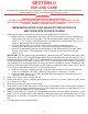

1700, 1720 AND 1740
ASSEMBLY INSTRUCTIONS
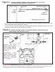
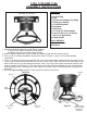
1. Assemble the bolts and nuts as per Figure 1 above.
a. Legs bolt to inside of shroud (6 nuts/bolts).
b. Bottom ring bolts to inside of legs (3 legs).
2. Wrench tighten. Make sure all 9 bolt sets are used and that the unit stands sturdily.
3. Go to pg. 9 for casting installation instructions. Refer to Figure 1, page 10 for hose assembly
instructions.
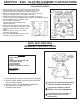
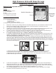
4. The 5 or 10 gallon cast iron pot supplied with your unit (if applicable) nestles into the top rings of the
cooker frame. When placing the cast iron pot on cooker frame, make sure the 3 foot extensions at the
base of the cast iron pot are placed inside the “inner” top ring of the cooker frame and outside of the
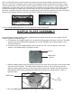
cooker’s shroud (see Figure 2.). The cast iron pot must be correctly installed onto the cooker frame
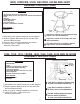
before adding food or cooking liquid. See Figure 3 for proper cast iron pot placement (10 gallon unit
pictured.)
5. Go to the Use and Care section of this manual for further instructions.
CONTENTS
(1) Bottom Ring
(3) Legs
(1) Shroud with Welded Top Rings
(1) Casting/ Air Shutter
(1) LP Hose/Regulator
(9) Bolts/Nuts
(1) Heat Plate
(1) 12” Deep Fry Thermometer
(1) Cast Iron Pot (5 or 10 Gallon)
and Lid (If Applicable)
(2) Lifting Hooks
TOOLS NEEDED:
Adjustable Wrench
Screwdriver
“Outer” Top
Ring
“Inner” Top
Ring
Shroud
Figure 1
Figure 2
Figure 3
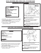
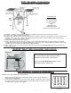
Lifting Hooks
(Used To Grasp
Eyelets for
Transport)
15
Eyelets
Top View
Heat
Plate
* Model May Vary From Picture