PO Box 1200 305 Commerce Drive Winfield, Alabama 35594 XB ROTARY MOWER OPERATOR AND PARTS MANUAL Part No 999996 www.kingkutter.
TO THE PURCHASER This manual contains valuable information about your new King Kutter Mower. It has been carefully prepared to give you helpful suggestions for operating, adjusting, servicing and ordering repair parts. Keep this manual in a convenient place for quick and easy reference. Study it carefully. You have purchased a dependable and sturdy mower, but only by proper care and operation can you expect to receive the service and long life designed and built into it.
It is the purchaser and/or operator’s responsibility to…. z Read and understand the information contained in this manual. z Operate, lubricate, assemble and maintain the equipment in accordance with all instructions and safety procedures in this manual. z Inspect the equipment and replace or repair any parts that are damaged or worn which under continued operation would cause damage, wear to other parts, or cause a safety hazard.
CONTENTS ITEM PAGE Safety ......................................................................... 6 Assembly Instructions ................................................ 8 Before Putting Into Service ...................................... 11 Safety Training ......................................................... 12 Operational Safety .................................................14 Transportation Safety ............................................... 16 Attaching To Tractor .......................
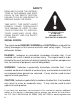
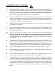
SAFETY READ AND FOLLOW THE INSTRUCTIONS IN THIS MANUAL AND ESPECIALLY IN THE SAFETY SECTION. FAILURE TO DO SO CAN RESULT IN SERIOUS INJURY OR DEATH. TAKE NOTE! THIS SAFETY ALERT SYMBOL FOUND THROUGHOUT THIS MANUAL IS USED TO CALL YOUR ATTENTION TO INSTRUCTIONS INVOLVING YOUR PERSONAL SAFETY AND THE SAFETY OF OTHERS.
EQUIPMENT SAFETY GUIDELINES z Safety of the operator and by standards is one of the main concerns in designing and developing a mower. However, every year many accidents occur which could have been avoided by a few seconds of thought and a more careful approach to handling equipment. You, the operator, can avoid many accidents by observing the following precautions and insist those working with you, or for you, follow them.
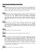
ROTARY MOWER ASSEMBLY INSTRUCTIONS STEP 1 With rotary mower lying flat on the ground, remove the wire holding lift pins and PTO shaft from mower. Remove bolts from the free end of the lift arm braces. Remove bolts attaching lift arms and lift arm braces to the mower. Remove bolt holding swivel link assembly from lift arm brace. STEP 2 Using the 5/8" x 3-1/2" bolt and the lift arm spacer, attach a lift arm to the front hole of the right side deck tube as seen in Figure A.
Figure A Figure B 9
ROTARY MOWER ASSEMBLY INSTRUCTIONS continued... STEP 8 At this time, tighten the four (4) 5/8" x 3-1/2" bolts attaching the lift arms and the lift arm braces to the mower. Also tighten the 5/8" x 6-1/2" bolt that joins them with the swivel link assembly. STEP 9 Lift the rear of the mower high enough for the tail wheels to be out of contact with the ground. Use blocks to ensure that the mower doesn’t fall. Loosen tail wheel arm adjusting bolts and jamb nuts.
BEFORE PUTTING ROTARY MOWER INTO SERVICE (IMPORTANT-INSTRUCTIONS PRIOR TO START UP) SHIPPED WITHOUT OIL IN GEAR BOX AND WITHOUT BEING GREASED. UNIT MUST BE SERVICED BEFORE USING. • • STEP 1 STEP 2 STEP 3 STEP 4 STEP 5 STEP 6 Fill Gearbox using Multi-Purpose Gear Oil (I.E. S.A.E. 80w/90 or S.A.E. 85w/140 Multi-purpose gear oil.) For all Grease Fittings use TYPE/grade II tube grease. Place mower so that the deck is secure and level.
SAFETY TRAINING z Safety is a primary concern in the design and manufacture of our product. Unfortunately, our efforts to provide safe equipment can be wiped out by a single careless act of an operator or bystander. z In addition to the design and configuration of equipment, hazard control and accident prevention are dependent upon the awareness, concern, prudence and proper training of personnel involved in the operation, transport, maintenance and storage of this equipment.
PREPARTION z z z z z z z z Never operate the tractor and mower until you have read and completely understand this manual, the Tractor Operator’s Manual, and each of the safety messages found on the safety signs on the tractor and mower. Personal protection equipment including hardhat, safety glasses, safety shoes, and gloves are recommended during assembly, installation, operation, adjustment, maintenance, repairing, removal, or moving the implement.
OPERATIONAL SAFETY z z z z z z z z 14 The use of this equipment is subject to certain hazards that cannot be protected against by the mechanical means or product design. All operators of this equipment must read and understand this entire manual, paying particular attention to safety and operating instructions, prior to using. If there is something in this manual you do not understand, ask your supervisor, or your dealer, to explain it to you. Most accidents occur because of neglect or carelessness.
OPERATIONAL SAFETY continued... z z z z z z z z z z Never allow the cutting blade to contact such items. Cut material higher at first, allowing finishing mower to clear hidden objects. Never assume an area is clear. Always Check! Always stop the tractor, disengage PTO, set brake, shut off the tractor engine, remove the ignition key, lower implement to the ground and allow cutter blades to come to a complete stop before dismounting tractor. Never leave equipment unattended with the tractor running.
OPERATIONAL SAFETY continued... z z Pass rotary mower diagonally through sharp dips and avoid sharp drops to prevent “hanging up” tractor and rotary mower. Practice will improve your skills in maneuvering on rough terrain. Always cut down slopes; never across the face. When using a unit, a minimum 20% of tractor and equipment weight must be on tractor front wheels. Without this weight, tractor could tip over, causing personal injury or death.
ATTACHING TO TRACTOR WARNING Never stand between tractor and rotary mower while backing up tractor to the hitch. STEP 1 Attach to tractor's category 1 three point hitch as described in the Tractor's Operator’s Manual. STEP 2 Determine if the PTO shaft needs to be shortened. NOTE: Due to the many variations in the tractor hitch points and distances between equipment gearbox input shaft and tractor PTO output shafts, some combinations may require PTO shafts to be shortened as described by the following steps.
ATTACHING TO TRACTOR continued... STEP 6 Raise rotary mower and remove blocking. Raise and lower rotary mower in order to locate the longest distance between equipment input shaft and the tractor PTO output shaft. With the rotary mower in the longest distance position shut down the tractor and SECURELY BLOCK THE ROTARY MOWER IN POSITION. STEP 7 As in step 5 hold PTO shaft sections together and check for a minimum of 6 inches of overlap.
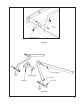
SIZING PTO SHAFT STEP 1 Cutting the PTO shaft to length. NOTE: Be sure to cut equal lengths of each PTO shaft section. Clamp end of PTO shaft in a vice and cut off shield where marked. (Figure 1-A & 1-B) Figure 1-A STEP 2 Using cut section of the shield as a guide cut shaft off the same amount. (Figure 2) STEP 3 Repeat steps 1 and 2 for other PTO shaft section. Figure 1-B STEP 4 Use a file to deburr PTO shafts. Clean up all chips, burrs and filings from both ends of the PTO shaft.
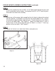
OPERATING INSTRUCTIONS CUTTING HEIGHT ADJUSTMENT To prevent blades from striking the ground your rotary should be set to the highest position that will give desired grass height. By setting your mower up this way you reduce blade wear and stress on the mower. Mowing at regular intervals will yield far better results than periodic mowing. (i.e. weekly vs. by-weekly mowing.) STEP 1 Raise rotary mower off the ground with the tractor and SECURELY BLOCK IN POSITION.
ROTARY MOWER OPERATION STEP 1 Before each use perform the maintenance described in maintenance section on page 24. STEP2 Read, understand, and follow the information on safety training, preparation, starting and stopping safety, operational safety, transport safety warning sections of this manual (pages 14 thru 18) STEP 3 With tractor running, lower rotary mower to ground so that the deck surface of the mower is parallel to the ground.
MAINTENANCE 1). Periodically check and maintain proper gear oil level. 2). Every 8 hours, grease wheel forks (4), wheel axles (4), PTO shaft universal joints (2), and PTO telescoping surface. NOTE: Use only a grade Type II tube grease. 3). Before each use check to make sure all safety features are installed and working properly. 4). Keep blades sharp and balanced at all times. When replacing blades, replace both blades and blade bolts at the same time. 5).
MAINTENANCE SAFETY Good maintenance is your responsibility. Poor maintenance is an invitation to trouble. Follow good shop practices. Keep service area clean and dry Be sure electrical outlets and tools are properly grounded Use adequate light for the job at hand. Make sure there is plenty ventilation. Never operate the engine of the towing vehicle in a closed building. The exhaust fumes may cause asphyxiation.
SAFETY SIGN LOCATIONS The types of safety signs and locations on the equipment are shown in the illustration below. Good safety requires that you familiarize yourself with the various safety signs, the type of warning and the area, or particular function related to that area, that requires your SAFETY AWARENESS REMEMBER: IF safety signs have been damaged, removed, become illegible or parts have been replaced without signs, new safety signs must be applied.
1 25
2 3 26
4 5 27
6 7 MODEL NO.
" PTO 147029 Ref. No.
XB KUTTER 30
Ref. No. Part Name Part Number 4' 1 CAT 1. Lift Pins (Pkg. of 2) 500001 2 3 4 5 6 7 8 9 10 11 12 13 14 15 16 17 18 Lift Arm LIft Arm Brace Swivel Link Kit (inc. bolt) Right Side Panel Kit (inc.bolts) Lift Arm Attachment Kit (inc. bolts) Gear Box Belt Guard Kit (inc. belt and strip) Belt Guard Left Side Panel Kit (inc. bolts) Tail Wheel Arm Spacer Kit Tail Wheel Arm Wheel Kit (inc. axle bolt) Tail Wheel Arm Fork Blade Bolt Set (Pkg. of 2) Mower Blade Set(Pkg.
40 HP GEARBOX 32
Ref. No.
NOTES:
1. Limited Warranty. King Kutter, Inc. (“King Kutter”), P.O. Box 1200, Winfield, Alabama 35594, warrants to the original retail purchaser (“Purchaser”) that the product that is the subject of this sale is free from defects in material and workmanship at the time of sale. Under this warranty, King Kutter will repair the defective product free of charge to the Purchaser, with either new or used and reconditioned replacement parts.