
Product Manual


8
ROTARY MOWER ASSEMBLY INSTRUCTIONS
STEP 1
With rotary mower lying flat on the ground, remove the wire holding lift pins
and PTO shaft from mower. Remove bolts from the free end of the lift arm
braces. Remove bolts attaching lift arms and lift arm braces to the mower.
Remove bolt holding swivel link assembly from lift arm brace.
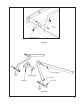
STEP 2
Using the 5/8" x 3-1/2" bolt and the lift arm spacer, attach a lift arm to the
front hole of the right side deck tube as seen in Figure A. Tighten only
finger tight at this time. NOTE: the lift arm should be on the gearbox
side of the deck tube and the lift arm spacer should be inside the
deck tube. Allow the lift arm to rotate until it rests against the gearbox
plate.
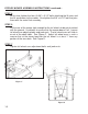
STEP 3
Using the 5/8" x 3-1/2" bolt, attach the right lift arm brace to the rear hole
of the right side deck tube. Tighten only finger tight at this time. NOTE:
the lift arm brace should also be on the gearbox side of the deck
tube. Allow the lift arm brace to rotate until it rests against the previously
installed lift arm.
STEP 4
Repeat steps 2 and 3 for the left side.
STEP 5
Insert the swivel spacer into the large hole in the swivel link.
STEP 6
Lift the right lift arm brace and hold while rotating the right lift arm forward.
Align the holes in the free ends of the linkages. NOTE: the lift arm
brace should be on the outside of the lift arm. Insert the 5/8" x 6-1/2"
bolt. Slide the swivel link assembly onto the free end of the bolt. The
bolt should travel through the swivel link spacer. Rotate the left lift arm up
and inset the bolt through the hole in it. Lift the left lift arm brace and slide
it onto the bolt. Place a lock washer on the bolt and screw on nut. Tighten
only finger tight. See Figure B.
STEP 7
Insert the lift pins in each lift arm and tighten.