PO BOX 1200 305 Commerce Drive Winfield, Alabama 35594 TG-48-XB ROTARY TILLER OPERATOR MANUAL Part No 999991 www.kingkutter.
TO THE PURCHASER This manual contains valuable information about your new King Kutter XB Rotary Tiller. It has been carefully prepared to give you helpful suggestions for operating, adjusting, servicing and ordering repair parts. Keep this manual in a convenient place for quick and easy reference. Study it carefully. You have purchased a dependable and sturdy tiller, but only by proper care and operation can you expect to receive the service and long life designed and built into it.
It is the purchaser and/or operator’s responsibility to…. Read and understand the information contained in this manual. Operate, lubricate, assemble and maintain the equipment in accordance with all instructions and safety procedures in this manual. Inspect the equipment and replace or repair any parts that are damaged or worn which under continued operation would cause damage, wear to other parts, or cause a safety hazard.
CONTENTS ITEM PAGE Safety ......................................................................... 6 Assembly Instructions ................................................ 8 Before Putting Into Service ........................................ 8 Safety Training ......................................................... 11 Transportation Safety ............................................... 15 Attaching To Tractor ................................................. 16 Sizing PTO .............................
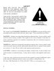
SAFETY READ AND FOLLOW THE INSTRUCTIONS IN THIS MANUAL AND ESPECIALLY IN THE SAFETY SECTION. FAILURE TO DO SO CAN RESULT IN SERIOUS INJURY OR DEATH. TAKE NOTE! THIS SAFETY ALERT SYMBOL FOUND THROUGHOUT THIS MANUAL IS USED TO CALL YOUR ATTENTION TO INSTRUCTIONS INVOLVING YOUR PERSONAL SAFETY AND THE SAFETY OF OTHERS.
EQUIPMENT SAFETY GUIDELINES Safety of the operator and bystanders is one of the main concerns in designing and developing a tiller. However, every year accidents occur which could have been avoided by a few seconds of thought and a more careful approach to handling equipment. You, the operator, can avoid many accidents by observing the following precautions and insist those working with you, or for you, follow them.
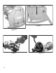
XB-ROTARY TILLER ASSEMBLY INSTRUCTIONS STEP 1 With rotary tiller still in crate, lay flat on a level surface. Cut banding straps on the two (2) upright crate posts. STEP 2 Remove the top & upper side sections of the crate, leaving the rotary tiller resting on the bottom section. You may take the tiller off of crate but you must swing stand arm down and lock in position. (See Figure A and B) Snap stand out of clip, straight out, then swivel the stand down to locked position.
STEP 4 Replace and tighten the (2) plugs and clean away any excess oil. STEP 5 Remove Breather Plug (Located at top of side gearbox, See (FIG. D point 1 on next page), there is also a plug at the bottom (Located in the side of the side gearbox) (FIG. D point 2 on next page) if oil comes out of lower plug, replace plug immediately and go to STEP 6 , if oil doesn’t come out of lower plug fill with gear oil (type GL5-85W 140) to lower plug. Replace and tighten the plugs. Clean away any excess oil.
Figure E Figure D Figure F 10 Figure G
SAFETY TRAINING Safety is a primary concern in the design and manufacturing of our product. Unfortunately, our efforts to provide safe equipment can be wiped out by a single careless act of an operator or bystander. In addition to the design and configuration of equipment, hazard control and accident prevention are dependent upon the awareness, concern, prudence and proper training of personnel involved in the operation, transport, maintenance and storage of this equipment.
PREPARTION Never operate the tractor and tiller until you have read and completely understand this manual, the Tractor Operator’s Manual, and each of the safety messages found on the safety signs on the tractor and tiller. Personal protection equipment including hardhat, safety glasses, safety shoes, and gloves are recommended during assembly, installation, operation, adjustment, maintenance, repairing, removal, or moving the implement.
OPERATIONAL SAFETY The use of this equipment is subject to certain hazards that cannot be protected against by the mechanical means or product design. All operators of this equipment must read and understand this entire manual, paying particular attention to safety and operating instructions, prior to using. If there is something in this manual you do not understand, ask your supervisor, or your dealer, to explain it to you. Most accidents occur because of neglect or carelessness.
OPERATIONAL SAFETY continued... 14 Never allow the tilling tines to contact such items. Never assume an area is clear. Always Check! Always stop the tractor, disengage PTO, set brake, shut off the tractor engine, remove the ignition key, lower implement to the ground and allow rotating pieces to come to a complete stop before dismounting tractor. Never leave equipment unattended with the tractor running.
OPERATIONAL SAFETY continued... Pass rotary tiller diagonally through sharp dips and avoid sharp drops to prevent “hanging up” tractor and rotary tiller. Practice will improve your skills in maneuvering on rough terrain. Always cut down slopes, never across the face. Always check tractor manual for proper use on slopes. When using a unit, a minimum 20% of tractor and equipment weight must be on tractor front wheels. Without this weight, tractor could tip over, causing personal injury or death.
ATTACHING TO TRACTOR WARNING Never stand between tractor and rotary tiller while backing up tractor to the hitch. STEP 1 Attach to tractor's category 1 three point hitch as described in the Tractor's Operator’s Manual. STEP 2 Determine if the PTO shaft needs to be shortened.
ATTACHING TO TRACTOR continued.... STEP 4 Pull apart PTO shaft and attach outer section to tractor PTO output shaft. NOTE: Be sure to pull on PTO shaft section to ensure yoke has locked into place. STEP 5 Place and hold inner PTO shaft section next to outer section and check if PTO shaft is too long. Each section should end approximately 3 inches short of reaching u-joint shield on the opposite section. If the shaft is too long measure 3 inches back from each u-joint shield and mark the other shaft section.
SIZING PTO SHAFT STEP 1 Cutting the PTO shaft to length. NOTE: Be sure to cut equal lengths of each PTO shaft section. Clamp end of PTO shaft in a vice and cut off shield where marked. (Figure 1 -A & 1-B) STEP 2 Figure 1-A Using cut section of the shield as a guide cut shaft off the same amount. (Figure 2) STEP 3 Repeat steps 1 and 2 for other PTO shaft section. STEP 4 Use a file to deburr PTO shafts. Clean up all chips, burrs and filings from both ends of the PTO shaft.
OPERATING INSTRUCTIONS STEP 1 Before each use perform the maintenance described in maintenance section (page 20). STEP2 Read, understand, and follow the information on safety training, preparation, starting and stopping safety, operational safety, transport safety warning sections of this manual (pages 12 thru 15). STEP 3 With the rotary tiller positioned on level ground, adjust the tractor lift arms so that when lifted, the rotor bar remains parallel to the ground.
NOTE: Do not allow the tractor engine or rotary tiller to bog down or stall. This causes undue wear and tear on the tiller and tractor. If this continues to happen reduce ground speed and raise tilling depth of rotary tiller. Never attempt to remove objects from the rotor bar until the tractor has been shut down and the tiller tines have completely stopped. WARNING Never travel at a fast ground speed while using the tiller, this could damage it.
MAINTENANCE SAFETY Good maintenance is your responsibility. Poor maintenance is an invitation to trouble. Follow good shop practices. Keep service area clean and dry Be sure electrical outlets and tools are properly grounded Use adequate light for the job at hand. Make sure there is plenty ventilation. Never operate the engine of the towing vehicle in a closed building. The exhaust fumes may cause asphyxiation.
SAFETY SIGN LOCATIONS The types of safety signs and locations on the equipment are shown in the illustration below. Good safety requires that you familiarize yourself with the various safety signs, the type of warning and the area, or particular function related to that area, that requires your SAFTY AWARENESS.
1 2 23
3 4 24
5 6 25
7 8 26
22” PTO 147122 Ref. No.
XB TILLER: EXPLODED VIEW 28
TG-48-XB TILLER PARTS LIST Ref. No. Part Name Part Number TG-48-XB 1 Lift Arm Brace 381001 2 Lift Arm (LH) 404404 3 Lift Arm (RH) 404405 4 Tail Rod Assembly 505116 5 Center Shield Assembly 505020 6 Lift Arm Spacer Kit 505021 7 Tine Pkg. (1-Right,1-Left) w/ Bolts 505002 7 Tine Pkg. (3-Right,3-Left) w/ Bolts 505006 7 4’ Complete Tine Pkg. (36 pcs.) 505036 8 Tine Bolt Pkg. (12 pcs.) 505012 8 Tine Bolt Pkg. (72 pcs.
TG-48-XB SIDE GEARBOX PARTS 30
TG-48-XB SIDE GEARBOX PARTS LIST Ref. No. Part Name Part Number 1 Side Gearbox Hub & Shaft w/Disc 100106 2 Hub N/A 3 Oil Seal (HMSA7 21632) N/A 4 Bearing (1209) N/A 5 Snap Ring N/A 6 Spacer N/A 7 Spur Gear (27 Teeth) N/A 8 Snap Ring N/A 9 Housing N/A 10 Bearing (6010) N/A 11 Snap Ring N/A 12 Spur Gear (38 Teeth) N/A 13 Gasket N/A 14 Gasket N/A 15 Pipe Plug 1/2” - 14 NPT N/A N/A 17 Pressure Relief Plug 1/2” - 14NPT N/A 18 Hex Cap Screw (M10 - 1.
TG-48-XB SERIES TOP GEARBOX PARTS 32
TG-48-XB SERIES TOP GEARBOX PARTS LIST Ref. No.
TG-48-XB HUB PARTS 34
Ref. No. Part Name Part Number 1 Hub N/A 2 Hub Stub Shaft w/Disc 100107 3 Bearing (6208) N/A 4 Oil Seal N/A 5 Snap Ring (40 x 1.5) N/A 6 Snap Ring (80 x 2.5) N/A 7 Gasket N/A 8 Mounting Plate N/A 9 Shield N/A 10 Cover N/A 11 Lock Washer (M10) N/A 12 Hex Cap Screw (M10—1.5 x 35) N/A 13 Nut (M10 -1.
1. Limited Warranty. King Kutter, Inc. (“King Kutter”), P.O. Box 1200, Winfield, Alabama 35594, warrants to the original retail purchaser (“Purchaser”) that the product that is the subject of this sale is free from defects in material and workmanship at the time of sale. Under this warranty, King Kutter will repair the defective product free of charge to the Purchaser, with either new or used and reconditioned replacement parts.