
Use and Care Guide


12
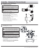
Assembly - Attaching the Accessories (continued)
Attaching the light kit tter assembly
2
□ Remove one screw (MM) from the light kit pan, and loosen,
but do not remove the other two screws.
□ Connect the wires from the light kit tter assembly (H) to
the wires from the fan motor assembly (E) by connecting the
molded adaptor plugs together. Carefully tuck all wires and
splices into the switch cup.
□ Push the light kit tter assembly (H) up to the light kit pan so
that the two loosened screw heads t into the keyhole slots.
Turn the light kit tter assembly (H) clockwise to secure.
□ Re-install the screw that was removed in the rst step.
□ Make sure all the screws are rmly tightened.
Installing the shatter resistant bowl
3
□ Place the shatter resistant bowl (I) into the light kit pan (G),
aligning the three at areas on the top of the ange of the
shatter resistant bowl (I) with the three raised dimples in the
light kit pan (G). Turn the shatter resistant bowl clockwise
until it stops.
WARNING: Do not overtighten when installing the shatter
resistant bowl into the light kit. Allow the shatter resistant bowl
to cool completely before removing.
I
G
H
G
E
MM