New Water ® Chlorine Pool Care System Models 400/430 for pools up to 40,000 gallons Model 120 for pools up to 25,000 gallons The New Water® Cyclers and Replacement Cycler Pacs Customer Service 800-222-0169 www.kingtechnology.
TABLE OF CONTENTS Introducing New Water® 3 Swimming Pool Tips 3 New Water® Cyclers 4 Parts List Above Ground Model 5 Parts List In Ground Models 6 Base Installation Model 120 7 Filter Installation Model 120 8 In-Line Installation Model 400 9 Off-Line Installation Model 430 10-11 Troubleshooting 12 Replacing a Cycler Pac 13 Setting Control Dial 14 Replacing Control Dial O-rings 15 Replacing Cap O-rings & Knobs 16 Winterizing 16 For Proper Performance
New Water® Thank you for choosing New Water®. This system will maintain a clean, clear swimming pool while you spend less time on maintenance and more time having fun! For In Ground Pools For Above Ground Pools New Water® Cycler The New Water® Cycler is on constant watch dispensing chlorine to control bacteria and provide a protective bank of sanitizer for your pool. Swimming Pool Tips Water Balance Guidelines Free Chlorine: pH: Total Alkalinity: Calcium Hardness: Total Dissolved Solids: Stabilizer: 1.
New Water® Cycler Installation The New Water® Cycler comes in several different models. Please review this list, determine which model you have and follow the appropriate installation instructions for that model only. IN GROUND - Off-line ABOVE GROUND POOLS ® ® 15 1/4" Cycler Model #430 Off-line for in ground pools ranging from 5,000 to 25,000 gallons. Uses a pre-filled chlorine pac, model 407C. Installation instructions are on pages 10 and 11.
Parts List • Model 120 1 2 8&9 3 4 10 7 12 SILICONE LUBRICANT 6 11 9 5 8 Included with New Water® 120 REF. # DESCRIPTION Replacement Parts for New Water® 120 QTY. INCLUDED 1 & 2 Cap w/O-Ring 1 3 Body 1 4 Pressure Relief Valve 1 5, 6, 7 Control Dial with O-Rings & Locking Pin 1 8 & 9 Knob with O-Ring 2 11 Mounting Base 1 12 Silicone Lubricant 1 REF. # PART NO.
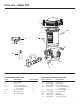
Parts List • Models 400 and 430 INCLUDED WITH • Model 400 and 430 REF. # DESCRIPTION QTY. INCLUDED 1&2 3 4 5, 6, 7 8&9 18 19 8 9 Cap w/O-Ring 1 Body 1 Pressure Relief Valve 1 Control Dial with O-Rings 1 Knob with O-Ring 2 Cap/Control Dial Tool 1 Silicone Lubricant 1 18 1 2 3 REPLACEMENT PARTS • Model 400 and 430 REF.
TOOLS NEEDED Above Ground, Base Installation - Model 120 Screwdriver Pipe Wrench • Install after all equipment and as far as possible from heater. • Any additional sanitizing equipment that is installed with New Water®Cycler must be installed after New Water®Cycler (never before) on the return line to the pool. PUMP FILTER ® Materials Needed Pipe Thread Tape or Sealant TO POOL The New Water®Cycler should always be installed between the filter and pool (or between heater and pool if applicable).
TOOLS NEEDED Above Ground, Filter Installation - Model 120 Screwdriver ® Pipe Wrench 1. 2. MATERIALS NEEDED Screw one end of nipple into the filter return. Pipe Thread Tape or Sealant Apply pipe thread tape or sealant to each threaded end of nipple. Hand tighten. Finish tightening by turning 1 to 2 revolutions with wrench. DO NOT OVER TIGHTEN. One 6” x 1 1/2” TBE PVC Nipple 5. Screw adapter into the other side of New Water®Cycler. Hand tighten.
In Ground, In-line Installation - Model 400 TOOLS NEEDED Pipe Wrench • Install after all equipment and as far as possible from heater. • Any additional sanitizing equipment that is installed with New Water®Cycler must be installed after New Water®Cycler (never before) on the return line to the pool. Hacksaw Do NOT install in copper pipe as chemical corrosion occurs. Tape Measure 12" to 15" ® ® OR MATERIALS NEEDED ® Bi-flow valve design allows water flow in either direction.
In Ground, Off-line Installation - Model 430 TOOLS NEEDED Screwdriver SCOOPS 2” – 36” APART Pipe Wrench ® Battery Operated Drill with 5/8” or 19/32” Bit When insufficient room for an in-line application, install off-line in straight pipe with scoops between 2” - 36” apart. Install as far from the heater as possible. • Install after all equipment and as far as possible from heater.
6. 7. 8. When pipe is totally dry, drill two 19/32” or 5/8” holes, between 2” - 36” apart, on the return line. Be careful not to go through other side of pipe. Cut tubing to size for each New Water® Cycler connection and attach one to each elbow with clamps. Tighten clamps with a screwdriver. Screw elbow into reducer bushings on both sides. 10. 11. Attach a gasket to each scoop. Place scoops inside holes so the inlet scoop faces the water flow and the outlet scoop faces away from the water flow.
Troubleshooting For more in-depth troubleshooting, go to www.kingtechnology.com Problem 1. What do I do if the water looks cloudy? Remedy 1. Make sure your filtration system is working properly (i.e. clean filter, skimmer and pump basket). 2. Make sure circulation time is adequate – increase pump 3. Make sure the pool is properly balanced (see page 3). 5. Make sure pool has a free chlorine reading of 1.0 to 3.0 ppm. 4. Shock the water to eliminate build up of any organic matter. 6.
Replacing a Cycler Pac MIN. 1. USE ONLY the factory recommended replacement New Water®Cycler Pac. (See label.) DO NOT USE any other pack or bulk chemical tablets in the New Water®Cycler. Use of any other product could result in over chlorination, bleached liners, unsafe pool conditions, fire or explosion. Warranty will be void if the correct New Water®Cycler Pac is not used. MAX Model 400 Model 120 Turn off pump. Turn dial to Minimum or 0.
Setting Control Dial This system is designed to work effectively with a variety of pool equipment as long as the following basic procedures are followed. control dial on New Water®Cycler by matching up the parameters of your pool on the chart below. THIS IS A STARTING 1. Set POINT ONLY and may need to be adjusted to fit your individual pool needs. See #2 below for adjusting directions.
Replacing Control Dial O-Rings Model 120 Models 400/430 Center of locking pin Center of locking pin 1. In the back of the New Water®Cycler depress center of locking pin with a finger and pull pin out of dial. 1. Using a needle nose pliers, find the snap ring tail located at approximately the 5 o’clock position under the control dial. 2. Pull down and out of the groove. 2. Turn control dial back and forth as you pull it out of the housing. Back o-ring SILICONE LUBRICANT 3.
Winterizing Replacing Cap O-ring 1. Hold cap in front of you upside down with the o-ring groove facing up. Place one end of o-ring into cap groove at the point closest to you. Hold o-ring down with the thumb and index finger of one hand. 2. Take hold of the far end of the o-ring with the thumb and index finger of the other hand. Roll o-ring slightly back towards you as you stretch the o-ring into the remainder of the cap groove. SILICONE LUBRICANT 3.
For Proper Performance 1) If using a multi-speed pump, run pump for at least 6 hours per day at high speed (at least 40 gpm). If the pump will run on low speed 24 hours per day or less than 6 hours per day on high speed, you must bleed the air while the pump is on by unscrewing the cap knob until water appears. Then screw the knob back on. Repeat this process each time the cap is removed for any reason. 2) Install system with 4-8 psi back pressure. Install T-fittings exactly as shown.
Limited One-Year Warranty King Technology, Inc. warrants to the original purchaser this unit will be free from any defects in workmanship and/or material, for a period of one (1) year from the date of original purchase. This warranty covers body, cap and control dial, but specifically excludes o-rings. King Technology at its option may replace any defective parts or the entire unit without charge after it is determined what is needed to correct any deficiency.