
Use and Care Manual


6. Follow the desired wiring diagram, as shown in Figure 5, to
connect the power supply to the heater using approved wire
nuts.
NOTE: When accessories are installed, use wiring diagram sup-
plied with the accessory.
7. If front cover was removed, reinstall by hooking the top edge
on the support bracket(s). Then push down to latch onto the
support bracket(s).
8.Replace wiring compartment cover(s).
9.Follow instructions accompanying thermostat for installation
and wiring thermostat. Visit www.king-electric.com for typical
thermostat wiring diagrams.
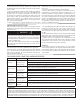
Instructions for Left or Right Side Wiring
Heater can be wired from either side - wire
one side only.
Cut one factory splice cap as shown.
This leaves two wires for power connection.
Caution: Do not cut both factory splice caps
on left side - you need only two wires for
power connection.
1.
2.
3.
4.
Cut to Apply Power to
LEFT SIDE
Cut to Apply Power to
RIGHT SIDE
Connection Diagram for Wall Thermostat
Connect power supply wires from wall thermo-
stat as shown.
Black and white supply wires can be connected
to the heater in reverse order. For simplicity
the
most common method is shown.
Connect bare groundwire to green groundwire.
1.
2.
3.
4.
5.
Power Supply Connection
LEFT SIDE
Power Supply Connection
RIGHT SIDE
SUPPLY WIRES
HEATER WIRES
SUPPLY WIRES
HEATER WIRES
Connection Diagram for Wall Mounted Single Pole Thermostat
1. Red thermostat wire to black power supply wire.
2. Black thermostat wire to black heater wire.
3. White power supply wire to white heater wire.
4. Connect all bare groundwires together.
BLACK WIRE
RED WIRE
BARE GROUNDWIRE
WHITE WIRE
WIRE COLOR CHART
Connection Diagram for Wall Mounted Double Pole Thermostat
Connect the two red thermostat wires to the black and
white power supply wires.
Connect the two black thermostat wires to the black and
White heater wires.
Connect all the bare groundwires together.
1.
2.
3.
Figure 5
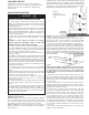
Figure 4
2 1/8"
Element
Air Guide
Self Drilling Screw
or Nail Location
Screwdriver Bit
or Nailing Tool
Location
Limit
Crossover Wire K Series
VOID in CB Series
The CB Series baseboard heater has the return wire within
the element and the wireway is empty. If your power supply is
on the right side you will need to cut the loop to apply your
power. If the power supply is on the left, cut one connector
to apply power supply similar to diagram in Figure 5.
For CB Ceramic Element Baseboard Heater Models
For K Series Element Baseboard Heater Models
Figure 5
_________________________________________________________________________________________
__________________________________________________________________________________________
___________________________________________________________________________________________