A WARNING: Read this instruction manual fully so as to become completely nil with the features of this product before operating, Failure to Operates this product correctly could result in damage to the product, personal property and cause serous injury. This is a sophisticated hobby product and is NOT a toy) It midst always be operated with caution: common sense and some basic mechanical ability.
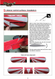
1. Aileron control surfaces installation: Star by using 8 shard hobby knife blade Wo cut through the covering and expose the lactose hinge chive. Inner supplied hinges into that slots and trial fit the aileron control surface on the wing panel.
Super Steersman 2: Wing strut and cabana strut metal fittings and attachments content: Upper right wing panel bottom surface Upper left-wing panel bottom surf any 1
per alderman | Wing installation: tube as shown.
5, Wing servo installation: Maxi 2mm screws You may use doy standard sie serve with a big om torque for the allergen control Use Off By minim self tipping screws 10 secure the servo to the Sara mount cover gs showman, Ensue the Servo control hom can move freely without mobbing the opening and tim the servo mount to iti required. M28 sellotaping sores if evangelizing looks dahlia, you may secure the wing send mounting cover to the wing panel with 4 off 2 x Bm self tapping screws.
Kink Hon Flasher refer the illustration for the correct argumentation and he exact mounting position.
Ip oot Balsa ane Wheel pants and Fairings installation: Wheel pant mounting plate Installation the sft wheel aide onto the left Landing gear hall as shown: Next install the wheel pant on wrwhesbaie and use the:holes on the met plate Bs template and dnl bed holes of the wheel gnat formfitting purposes. Then install a wheel collar bo the aie followed by wheel Lock the wheel collar on the axe by tightening the grub sowers. Finally.
l 9. Landing Gear installation: Ins bol Landing seat halves ihe bigotry of the fuselage and stone the min place using the supplied 8 hex screws.
er. Ste airman AMD BALSAMIC RARE : Iwo Horizontal Stabilizer Installation: Inserted the stabilizer int the slot as shown, see pliers A Once aligned. use a fine felt oped pen to gos the outline of the fuselage on the top and nation of the stabilizer, see picture B.
In Ultraconservative linkage installation: Install 3 control Bordon he underside of the thou hand elevator halve as shown below and glue wio place. Ensure the clevis mounting hole is aligned fo the binge Ine fo achieve a symmetrical contra] throw Then sin the hinges to stall both elevator Salves to the stabilizer: Meuse ensure the Shagged joining wie i located through te slot and inserted into he elevator halves as shown: Note: The 2 valorous halves must Be natal and carelessness to.
11. Elevator servo and linkage installation: Brit you need fo make a slam Colin he tm covering malted oi he push rod edt in order dodo this neatly: gently inset the supplied 90 8 im piano wire (hon clevis side) into the push rod sieve in the racial compartment and slowly feed the plant wire until | niches the Sim coven: This will lel you knew exact where the push rod ed! is at the rea of the fuselage Next gat a hobby blade io make a small cut in the fim covering and labile wire exit rom ihe corning.
| 12. Tail wheel fairing assemble First use a straight sandbagged a pen lo marks fine on the covering fim This ne extends from the cutout al the tear Di the fuselage as shown. fr stall the flying wire mounting plate by acing he Supplied 2.8 x 6mm self tapping screws to Secure it in place. 4 Her bail ft the tall wheel plastic cover onto the fuselage and anal as shown You may use the white color im on the covering to align 1 properly.
insert ie tal wheel ink he metal bracket push mE the pin through the Bracket and the wheel Ee 1 using plies inserts 5 Cochin into the groove on 7 Miss each side of the pin. A hek sores Please note: The hinge and the scale misshaped fodder control bof bas to be installed poor to he rudder installation.
|. Flying wires rigging: Ld ot Trial it the flung wires between the vertical fin and the stabilizer Ensure the management js straight and fire before vou secure the clevis onto the push rod with Cage.
Je. Bottom wing installation: Lover wing joiner lube insert the lower wing pine tube through the sleeve in the fuselage Then slide the left wing onto the wing hoer tube unlit isotope Boa inst the wing saddle Sea pic 21 reticence the wing locking tab Hag aligned with the hole in 8 wing bunting boy (See plo #21. Finally lock the wing In place by using the supplied M3s8 screw Please follow the same procedure to install the righting Pic #8 shows How beauty the LR wing are mounted oi the fuselage when composts.
l 18. Mainsprings, wing struts and aileron control rod linkages setup instruction Fling wires U Length 400mm 8 pes Prepare a parole aileron pushiness as = shown. Ling wes © Oem —0 IL lobar noes oes You may fer lo the flying wires rigging drawing shown above forth installation. > Attach the top wing and lion the per-installed metal Tings in the fuselage ib front olive cockpit with the cabana struts.
Superstardom A coos BALSA REF | 19. interconnect push rod installation for ailerons: Maxi Z screws Mix sores Fist set the lower wing ailerons al neutral vou canister masking tape to Holt them in place Then connect he push rod between the upper and lover wing ailerons Theodosius length of the push rods so that the wip ailerons are neutral when the bottom ales sensual 8 Le L Hare are some more pics Ke voluble have a better understanding of the ling wires connections.
Nation: Mau 12 screws Choose your devised motor according le commensurable power range.
| 21.
i 22. Canopy and cockpit installation: ‘We have made a very detailed scale instrument panel. Cockpit ares and plo: Most of the hard work in fis rea has been done Tor you, however you still need 1 spend a ills Hume and effort io assemble this scale detail Time spent on this && well work iE and gives the model a very realistic look. To install the instrument panel into the cockpit vou must first remove the collision sick.
TIMEOUT BALSA ARE per Steersman i 23.
Blurring hols for the Cowling Mix Mounting bail forth Cowling Adumbrating is supplied which replicates the Tull engineering as closely as possible: His made of vacuum molded pans and other lightweight components to keep the weight 10 8 minimum.
Lie scissors to cul out the decals. Cutout and tiny the required decal as shown above: N Position the decal precisely In the designated spot. Pel off the backing paper Anonymity 10 Ihe covering Him and use your Anger fo tightly press undo colas then ral over with a cloth. Unite in pace petiole the positive protective film very showy: Success H The decals now adhered family in plats.