Bay Networks Extranet Switch 2000 Getting Started Guide
Bay Networks Part Number: 301461-B Rev. 00 Date: April 1998 Accuracy Notice The products and specifications, configurations, and other technical information regarding the products contained in this document are subject to change without notice.
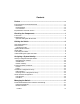
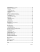
Contents Preface .....................................................................................................v Extranet Switch Documentation Map ........................................................................... vi Conventions .................................................................................................................... vii Documentation ........................................................................................................... vii User Interface .....
Display Setting ........................................................................................................... 17 Extranet Switch Welcome Display................................................................................ 18 Preparing for Configuration .......................................................................................... 20 Quick Start..................................................................................................................
Preface This Getting Started Guide will step you through the necessary tasks to get your Switch up and running fast. This guide provides information on the following: • Components • Cabling, Lights, and LEDs • Assigning a System Identity • Accessing a Web Browser • Managing the Switch • Rack Mounting • Changing Hardware Configurations Complete details for configuring and monitoring the Switch are in the Bay Networks Extranet Switch Administrator's Guide.
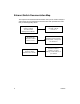
Extranet Switch Documentation Map This map lists the associated documentation that you will need to configure and manage your Bay Networks Extranet Switch and represents the order that you would typically follow.
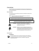
Conventions This guide refers to the Bay Networks Extranet Access Switch 2000 as the Switch. This document assumes that you are familiar with Web browsers and their general operation. Documentation This document uses the following conventions to distinguish among notes of varying importance: NOTE: Take notice. Notes contain helpful suggestions or references to materials contained in this document. TIP: Good idea.
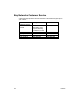
Bay Networks Customer Service Contact the appropriate Technical Solutions Center below to get help on your Switch.
Chapter 1 Checking the Components Before you begin cabling and configuring the Bay Networks Extranet Switch, examine the product packaging to be sure that you have all the necessary components. Front View Following is a front view of the Switch.
Components List The following table lists all of the components and accessories of the Bay Networks Extranet Switch 2000.
Chapter 2 Cabling the Switch This chapter describes how to connect the cables that you must use with the Switch, including pinouts for local area networks (LAN) connections, and how to read the LEDs when the Switch is powered on. LAN Speed Selection The Switch automatically determines the speed of the LAN connection during power-up. To change the speed simply power down the Switch, connect to the desired LAN, and power the unit back up.
Connector Pinouts The LAN connectors on the Switch are RJ-45 straight-through. The following illustration shows the Switch connector's 10/100BASE-TX pinouts. Figure 2 − 10/100BASE-TX Pinouts Optional WAN Interface The WAN connectors are located on a PCI card that is installed in the switch. Two DB26S connectors provide the signals needed to interface to V.35 equipment. Included in the accessory box are two cables that map the DB26S signals to a standard V.35 connector. The cable pin-outs are shown below.
Note that you will need a DSU/CSU (digital service unit/channel service unit) between the WAN connection and the Switch. Serial Cable The serial cable provided with the Switch is a DB9/DB25-to-DB9/DB25. This provides a cross-over (transmit-to-receive and receive-to-transmit). The DB9 connector goes into the Switch and the other DB9 or DB25 connector goes into your workstation or terminal. You should ignore the extra DB25 connection that is attached. Connecting the Cables 1.
Understanding the Lights and LEDs The Power light is green when the power is on; if it is flashing, there is a hardware failure and you should contact Bay Networks. The Reset light is green, and when it flashes the Switch is either reading or writing to the disk. You can press the Reset button to restart the Switch, however, Bay Networks recommends that you restart the Switch from the System Shutdown display (refer to the Administrator's Guide for details).
Figure 6 − 10/100BASE-TX LAN LEDs 10/100BASE-TX LAN LED Card Indicators LED Indicator Description LNK On The cable connections between the card and the device to which this interface is attached are good. Off The cable connections between the card and the device to which this interface is attached are faulty. On or Flashing The card is sending or receiving network data. The frequency of the flashes increases with increased traffic. Off The card is not sending or receiving data.
Chapter 3 Assigning a System Identity This section describes two methods, IP Address Configuration Utility and Serial Interface Configuration Procedure, that allow you to assign a Management IP Address, subnet mask, and optional default gateway address to your Extranet Switch. The Management IP Address is the address that is used for all system services, such as HTTP, FTP, and SNMP. The Management IP Address will enable you to manage the Switch from a Web browser.
Startup Configuration Requirements This section provides descriptions of the fields that you must complete with either the IP Address Configuration Utility or the Serial Interface Configuration procedure. Management IP Address Enter a Management IP Address for the system. You need this address to manage all system services, such as HTTP, FTP, and SNMP. This address must be accessible from one of the Switch's private physical interfaces.
Private and Public Interfaces The Bay Networks Extranet Switch provides secure access between your local area network (LAN) and Public Data Networks like the Internet. Throughout this document the term Private refers to the LAN within your corporation, and the term Public refers to Public Data Networks. This concept is important because the Public interface accepts only tunneled protocols, while the Private interface accepts both regular (nontunneled) and tunneled protocols.
IP Address Configuration Utility Bay Networks provides a utility to perform the initial configuration of a Switch. Requirements To assign the Switch a Management IP Address with the Bay Networks IP Address Configuration Utility you must have the following: • A PC running Windows 95 or Windows NT with a functioning TCP/IP stack. • The PC must be running on the same subnet as the Switch that is to be configured, and it must have an operational network connection.
The following display appears while the program searches for a Bay Networks Switch that has not been configured with a Management IP Address and subnet mask. Figure 8 − Serial Number Search Display 2. The program automatically enters the Serial Number for the first Switch discovered into the table of discovered Switches. Figure 9 − IP Address Configuration Utility Display 3.
4. Click Apply to configure the Management IP Address, Subnet Mask, and Default Gateway on the Switch. The IP Address Configuration Utility display disappears. When the Switch has completed updating its configuration with the Management IP Address, Subnet Mask, and optional Default Gateway, your default Web browser will automatically open to the Bay Networks Extranet Switch Welcome display. 5. Click Close to shut down the IP Address Configuration Utility.
Procedure 1. Connect the serial cable from the Switch’s serial cable port to a terminal or a communications port of a PC. 2. Using a terminal emulation program, such as Hyper Terminal, press the Enter key and you are prompted to enter a user name and password.
A Sample display follows: Welcome to the Bay Networks Extranet Switch Copyright 1998, Bay Networks Date: 4/29/98 Unit Serial Number: 01001 Please enter the administrator's username: admin Please enter the administrator's password: setup 1) Management IP Address 2) Management IP Subnet Mask 3) Gateway IP Address 4) Allow HTTP Management C) Controlled Crash E) Exit Please select a menu choice (1 – 4, C, E): Figure 10 − Sample Serial Interface Display 4. Once you complete the configuration, type E to Exit.
Chapter 4 Managing the Switch This chapter describes the recommended Web browsers, the default login and passwords to gain access to the Bay Networks Extranet Access Switch, and the Quick Start Configuration. Recommended Web Browser Versions and Settings Bay Networks Extranet Manager uses Java, JavaScript, and HTML features. For the management interface to function properly, verify that your Web browser meets the following minimum requirements. Platforms Supported Windows 95, Windows NT, or Macintosh.
Extranet Switch Welcome Display The Welcome display allows you to enter any of the three configuration areas for the Bay Networks Extranet Switch, including: • Quick Start Configuration • Guided Configuration • Manage Extranet Switch • Registration • Notebook Before entering the configuration options, you should first register to activate licenses, warranties, and services. Figure 11 shows the alternatives you have when first configuring your Switch.
Figure 12 shows a sample Extranet Switch Welcome display. Descriptions of each configuration option follow. A detailed checklist describes things you will need to properly configure your Switch. Then full details of the different procedures are described. Complete details for configuring and monitoring the Switch are in the Bay Networks Extranet Switch Administrator's Guide.
Preparing for Configuration To properly prepare for Installation and Configuration of the Bay Networks Extranet Switch, you should have the following items available: A Management IP Address for the system. You need this address to manage all system services, such as HTTP, FTP, and SNMP. An IP Address for the LAN port that is available on the system board. Any number of Public IP Addresses; e.g., one IP address for each Public LAN Interface and one IP address for each T1 WAN interface.
Guided Configuration Click to begin the Guided Configuration. This option allows access to all Configuration Management facilities. However, the design and structure of the Guided Configuration is best followed using the top-to-bottom layout provided. This approach walks you through the entire Navigational Menu from the Profiles to the Admin selections. Each functional area begins with a summary of the objectives of the area and then steps you through the area (e.g., Profiles), one subsection at a time.
Logging in and Supplying a Password Start up a Web browser and enter your Switch's Management IP Address. Select an option in the navigational menu and submenu, and then you are prompted for the Login and Password. Enter the system default Login and Password in lowercase characters, as follows: Login: admin Password: setup IMPORTANT: If you change your password and later need to access the Serial Interface Configuration, you must then enter the modified password.
Quick Start Configuration Prerequisites This display acts as a checklist for you to prepare for the Quick Start Configuration. Assembling the information beforehand, and verifying that you can establish a PPTP Client session, makes the Quick Start easy.
Required Environment This section describes the environment you must be using to perform the Quick Start Configuration. If this does not describe your environment, use the Guided Configuration. Point-to-Point Tunnel Protocol (PPTP) tunnel access method PPTP is a tunneling protocol supported by Bay Networks, Microsoft, and other vendors. The PPTP client is available for Windows 95 on the Bay Networks CD and comes with Windows NT 4.0 and later.
Prerequisites • • IP configuration information (refer to Startup Configuration Requirements on page 10 for additional information). − A Management IP Address for the Switch − Subnet Mask for the local subnet User IDs and Passwords − PPTP Users (up to 3) − Administrator Post-Configuration Testing • A PPTP remote user dialing in from an external system.
Configuration This display allows you to add a LAN port IP Address and Subnet Mask, establish the tunnel as Private (your private LAN) or Public (public data networks), and configure up to three PPTP Users and an Administrator with User IDs and Passwords. Additionally, you can set the system’s Date and Time.
LAN/WAN Interfaces Interfaces Lists the Management IP Address, LAN port, and any LAN or WAN cards that you have installed in the Switch. IP Address Enter an IP address for each interface on the Switch, including the LAN port. These IP addresses are used for tunnel creation. The IP Address consists of 32 bits, which are written as four octets in dotted-decimal format. For example: 192.168.34.
Type The default configuration for Switches assigns the Management LAN interface as Private, and the LAN and WAN card interfaces as Public. Public Indicates that this interface is attached to a Public data network like the Internet. The Switch rejects nontunneled protocols and only accepts tunneled protocols like IPsec, PPTP, L2TP, and L2F and the diagnostic protocol PING on a Public interface. A host can send only enough packets to a Public interface to establish a tunnel connection.
Remote User Static IP Address Enter an IP Address to be assigned to this user when establishing a PPTP tunnel session. Note that this IP Address is unnecessary if you assign user IP addresses from either a DHCP server or an internal address pool. Administrator The Administrator Settings allow you to change the Primary Administrator User ID (UID) and Password. The Primary Administrator User ID and Password combination always has access to all displays and controls.
Automatic Backup The Automatic Backup display under the Manage configuration option allows you to configure regular intervals when your system files are saved to designated host backup file servers. IMPORTANT: You should configure Automatic Backups immediately so that you will not lose system or configuration information in case of problems. You configure the Automatic Backup servers from the Admin→Automatic Backup display.
Extranet Access Client Installation Windows 95 To install the Bay Networks Extranet Access Client onto a Windows 95 PC, you must first copy and install four files that are on the Bay Networks Extranet CD in the Client folder. International software users should note that you must go to the Microsoft web site http://support.microsoft.com/support to get the MSDUN12 patch. 1. First, install Msdun12.exe (Microsoft Dial-up Networking update) by double-clicking on the file name.
B. Under the same box titled “The following network components are installed,” make sure that NetBEUI is not installed. To verify this, scroll down through the list box and look for any lines that have NetBEUI in them. If there are any lines that include NetBEUI, click on the line, and then click on the Remove button. This forces the Network Neighborhood to use NetBIOS over TCP/IP, which is compatible with the Extranet Switch. C.
Windows NT 4.0 To install the Bay Networks Extranet Access Client onto a Windows NT 4.0 PC, you must first copy and install the Extranet Access Client (Eac_10d.exe) that is on the Bay Networks Extranet Switch CD in the Client folder. 1. Install Eac_10d.exe by double-clicking on the program name. The installation is self-explanatory. As prompted at the end of the installation, reboot your system. 2.
Chapter 5 Rack Mounting This chapter describes two methods you can use to mount your Switch into a chassis rack. • Rack-mount brackets for use with a two-post rack (page 36). • Sliding rails for use with a four-post rack (optional purchase). Following are standard rack-mounting considerations that Bay Networks recommends you follow: • The maximum recommended ambient temperature is 40 degrees Centigrade. Additionally, make sure the internal temperature of the rack does not exceed 40 degrees.
Mounting Brackets The following illustration shows mounting brackets being attached to a Switch in preparation of a two-post rack mount installation. Position the brackets with the rack-mount bracket facing outward (as shown below). Optionally, you can mount the brackets in the rear of a rack.
Rack Mount Installation Procedure Bay Networks recommends that you have two people available when installing the rack-mount brackets. 1. Position the bracket onto the Switch (as shown on the previous page), then screw in the four rack-mounting screws. Repeat this step on the other side of the chassis. 2. With one person holding the Switch in place, insert the two front screws on each side to secure the Switch and brackets into the rack.
Sliding Rails (Optional) The following illustration shows the optional sliding rail assembly that enables you to slide the Switch out of the rack and lift off the top cover for interior access. Note that the sliding rail kit is optional and is separately orderable. NOTE: You must have a four-post rack to use the sliding rail mount assembly, and the rack must be at least 20-inches deep. Optional extender brackets and hardware are provided in case your rack is deeper than 20 inches.
R ack M ounting S crew s R ack M ounting B racket(s) M ounting R ail Figure 16 − Sliding Rail Installation for a Four-Post Chassis Rack Mount Rack Mounting 39
Sliding Rail Installation Procedure NOTES: • Insert all bracket mounting screws so that the screw heads are inside the slides. • Do not use washers on the inside of the slides. • Mount the side brackets parallel to each other. • Determine if the unit will slide to the front or rear of the rack. These instructions are for sliding the chassis forward; reverse the closed-end bracket for rearward travel. 1. Separate the slide rails from the rail bracket by pressing down on the lock-release spring. 2.
Chapter 6 Changing Hardware Configurations This chapter describes how to change existing hardware configurations, including: • Installing LAN or WAN cards or adding memory. • Swapping out a power supply. NOTE: Wear an antistatic band when handling electronic components for the Switch to avoid damaging them. WARNING: Turn off the Switch and unplug it before installing LAN or WAN cards, system memory, or installing a new power supply.
1 R em ove the three screw s from top of cover 2 Lift rear of cover up, and pull aw ay from unit. Figure 17 − Removing the Top Cover 1. Turn off the Switch's power and unplug it. 2. Remove the three screws at the top rear of the chassis. 3. Slide the top cover back and move it away from the chassis.
System Board Figure 18 shows the Switch's System Board, in particular the DIMMs, Option Cards Slots, Cooling Fans, and Replaceable Battery are noted. Figure 18 − Switch's System Board WARNING: Beware of danger if the battery is incorrectly replaced. Replace with the same or an equivalent battery only, as recommended by the manufacturer. Also, dispose of used batteries according the manufacturer's instructions.
Installing Option Cards The following illustration shows you how install LAN or WAN option cards into the Switch. You can use Slots 1 to 3 for any mix of LAN and WAN cards. Note that Slot 4 is not supported. Figure 19 − Installing LAN or WAN Cards 44 1. Power off the Switch. 2. Remove the filler panel screw and pull out the filler panel. 3. Slide the option card into the intended slot. Make sure the card seats firmly and evenly into the card slot.
Installing Additional DIMMs The following illustration shows you how to unlock a Dual Inline Memory Module (DIMM), and remove or install a DIMM. Install DIMM in the next available slot (i.e., if the DIMM # 1 slot is populated, then add the next DIMM to the DIMM # 2 slot). Figure 20 − Installing Additional Memory 1. Power off the Switch. 2. Press down the locking levers on both sides of the DIMM. 3. Pull the DIMM up to remove it from the slot. 4.
Memory Options The Switch ships with 64-MB memory installed. In case you want to increase the memory, this table lists memory from different vendors that has been tested with the Switch's System Board, and the vendor's accompanying part number. 46 Vendor 2M x 72 (16Mb), Buffered ECC - 60ns Micron Technology Kingston Technology Corp. PNY Part Number MT9LD272G-60X KTM2x72V82-60EG 722086EDM2G11TC 4M x 72 (32Mb), Buffered ECC - 60ns Micron Technology Samsung Kingston Technology Corp.
Replacing a Power Supply Turn off the Switch before attempting to replace a Power Supply. Replacing a power supply involves the following steps: 1. Remove the top cover (three screws). 2. Remove the four exterior screws that secure the Power Supply to the rear of the Switch. 3. Detach the connectors from the following devices: − − − Processor board Hard disk drive(s) Recovery diskette drive 4. Swap out the faulty power supply. 5. Reattach all cables and screws.
Removing the Front Bezel The following illustration shows you how to remove the front bezel from the Switch. You must remove the bezel to insert the Recovery Diskette. 3 .5 - in c h D is k D r iv e S lid e fin g e r s b e h in d fr o n t b e z e l a n d fir m ly p u ll fo r w a rd in th e d ir e c tio n o f a rr o w s .
Note that the first few times you remove the front bezel it might seem to resist removal. This is simply because the pins and snaps are new. After a few times, removal is easier. Sliding the top cover back is optional; it allows you to get a better grip on the front bezel for removal. Remove the Switch front bezel as follows: 1. Optionally, remove the three screws at the top rear of the chassis, then slide the top cover back. 2. Slide your fingers between the front bezel and the Switch. 3.
Removing the Hard Disk Drive The following illustration describes how to remove a Hard Disk Drive from the Switch.
Replacing the Hard Disk Drive The following steps describe Replacing the Hard Disk Drive. 1. Reattach the four screws securing the drive to the disk drive tray. 2. Put the disk drive tray back inside the chassis and slide it back over the two standoff screws. 3. Replace the two front screws, which draws the disk drive tray to the front of the chassis. 4. Tighten the two standoff screws. 5. Attach the DC power cable at the bottom to the hard drive. 6. Attach the hard drive ribbon cable.
Appendix A Specifications Physical Depth: 17 in. (43.18 cm) Width: 16.75 in. (42.55 cm) Height: 7.00 in. (17.78 cm) Weight: 25.0 lbs. (11.34 kg) Electrical: 110-120/220-240V, 6.0/3.
Appendix B Special Notices This appendix provides information on statements of conditions, the Bay Networks Software License Agreement, and RADIUS attribution. Statement of Conditions In the interest of improving internal design, operational function, and/or reliability, Bay Networks, Inc. reserves the right to make changes to the products described in this document without notice. Bay Networks, Inc.
EC Declaration of Conformity This product conforms (or these products conform) to the provisions of Council Directive 89/336/EEC and 73/23/EEC. The Declaration of Conformity is available on the Bay Networks World Wide Web site at www.baynetworks.com. Voluntary Control Council for Interference (VCCI) Statement This is a Class A product based on the standard of the Voluntary Control Council for Interference by Information Technology Equipment (VCCI).
Bay Networks, Inc. Software License Agreement NOTICE: Please carefully read this license agreement before copying or using the accompanying software or installing the hardware unit with pre-enabled software (each of which is referred to as “Software” in this Agreement). BY COPYING OR USING THE SOFTWARE, YOU ACCEPT ALL OF THE TERMS AND CONDITIONS OF THIS LICENSE AGREEMENT. THE TERMS EXPRESSED IN THIS AGREEMENT ARE THE ONLY TERMS UNDER WHICH BAY NETWORKS WILL PERMIT YOU TO USE THE SOFTWARE.
3. Limited warranty. Bay Networks warrants each item of Software, as delivered by Bay Networks and properly installed and operated on Bay Networks hardware or other equipment it is originally licensed for, to function substantially as described in its accompanying user manual during its warranty period, which begins on the date Software is first shipped to Licensee.
Bay Networks the Software, user manuals, and all copies. Bay Networks is not liable to Licensee for damages in any form solely by reason of the termination of this license. 8. Export and Re-export. Licensee agrees not to export, directly or indirectly, the Software or related technical data or information without first obtaining any required export licenses or other governmental approvals.
RADIUS (Remote Authentication Dial In User Service) Livingston Enterprises, Inc. 6920 Koll Center Parkway Pleasanton, CA 94566 Copyright 1992 Livingston Enterprises, Inc. Permission to use, copy, modify, and distribute this software for any purpose and without fee is hereby granted, provided that this copyright and permission notice appear on all copies and supporting documentation, the name of Livingston Enterprises, Inc.
Index 1 10/100BASE-TX LAN LEDs, 7 100BASE-TX interface, 3 10BASE-T interface, 3 A additional memory installing, 41 administrator, 25 administrator settings, 29 antistatic, 41 automatic backup, 30 DHCP, 24 dimensions of Switch, 51 DIMMs, 43 installing, 45 diskette IP Address Configuration Utility, 12 documentation map, vi DSU/CSU required, 5 E electrical, 51 F B front bezel removing, 48, 49 Bay Networks Customer Service, viii Bay Networks Extranet Switch Administrator's Guide, 19 G C Category 3, 4 w
J R Java, 17 rack mount, 36 installation procedure, 36 recovery diskette drive, 48 registration, 18, 21 relative humidity, 51 RJ-45 pinouts, 4 L LAN cards, 27 installing, 41, 44 LDAP, 24 LEDs system board, 6 length, 51 login default, 22 M Manage Extranet Switch, 18, 21 memory 64-MB, 46 memory, increasing vendors, 46 Microsoft Internet Explorer, 17 N Netscape cache settings, 17 O option card slots, 5 option cards slots, 43 P password default, 22 power cords connecting, 5 PPTP, 24 private, 11 defined,
time, 29 top cover removing, 41, 42 U user ID, 28 user interface, vii W installing, 41, 44 WAN connection DSU/CSU, 5 warning, vii Web browser, 14 Web browsers recommended, 17 weight, 51 Welcome display, 18 width, 51 WAN cards, 27 61