6900 Series 2.4GHz Long Range Wireless LAN Access Point / Bridge Installation and Operation Manual Ver 1.
PROFESSIONAL INSTALLATION REQUIRED The 6900 Series must be installed as a system by experienced antenna installation professionals who are familiar with Radio Frequency (RF) issues such as gains and losses, as well as local building and safety codes. Failure to do so will void the product warranty and may expose the end user to excessive RF hazard. Regulations regarding maximum antenna gains, power output and maximum permissible exposure vary from country to country.
FCC Caution This device and its antenna must not be co-located or operating in conjunction with any other antenna or transmitter. This device complies with Part 15 of the FCC Rules. Operation is subject to the following two conditions: (1) this device may not cause harmful interference, and (2) this device must accept any interference received, including interference that may cause undesired operation.
Table of Contents PROFESSIONAL INSTALLATION REQUIRED........................................................ 1 MICROWAVE RADIO RADIATION WARNING ........................................................ 1 Federal Communications Commission (FCC) Interference Statement ............... 1 Table of Contents..................................................................................................... 3 Chapter 1 Overview .......................................................................................
Chapter 1 Overview 1.1 Introduction to the 6900 Series The 6900 Series is a powerful answer for customers seeking a reliable high- speed wireless connectivity solution. It is a 2.4GHz IEEE 802.11b/g-compliant Wireless Bridge/AP/AP Client, data delivers 1 to 54 Mbps data rates without the need for a license. 6900 Series can operate as a point-to-point or a point-to-multipoint bridge to link networks in different buildings.
1.
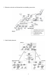
◎ Education schools and Universities inter-building connection ◎ Public-Safety Network 6
◎ Building to building connection 7
1.4 The 6900 series operation types There are two different modes in which you can set up the 6900 series in the building-to-building wireless network: Point to Point mode, and Point to Multipoint mode. ◎ Point-to-Point Connectivity (PTP Mode) This is the simplest network configuration in which several computers equipped with the PC cards or client bridges that form a wireless network whenever they are within range of one another.
1.5 The 6900 series Package Content Open the package carefully, and make sure that none of the items listed below are missing. Do not discard the packing materials, in case of return; the device must be shipped in its original package.
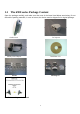
2.1 Chapter 2 Hardware Installation Hardware Description ◎Outdoor unit A. B. C. D. E. F. G. H. I. Two layers silica gel: having double-waterproof EMI prevent wire: To avoid electromagnetic interference Nylon cable gland:IP68;Working Temp:-40℃~100℃ Half-screw: Not to fall Panel Antenna:14dBi or 17 dBi gain;SMA connector Access Point/Bridge:IEEE 802.11b/g-compliant Power over ethernet(POE) Splitter set: Output 12vdc/1.
LED Power Wireless Color Green Green Activity LAN Link/Activity Green Green Status On Off Flash Off On Flash Off Description Power is supplied No Power. Antenna is transmitting or receiving data. Antenna is not transmitting or receiving data A valid link is established It is transmitting or receiving data No link is established ◎ Indoor unit DC injector A. B. C. D. Power LED: The Light is green.
Step 2: Ethernet cable to connect POE Splitter set Step 3: POE Splitter set to connect AP/Bridge Step 4: Antenna to connect AP/Bridge Step 5: To screw the housing 12
2.
2.4 Indoor Unit Installation Chapter 3 Quick Start - First time use 3.
3.2 To set the Base Station unit (BU) PC Configuration Follow the steps below in order to configure the TCP/IP settings of your PC. Step 1. In the Control Panel double click Network Connections, and then double click on the connection of your Network Interface Card (NIC). You will then see the following screen. Step 2. Select Internet Protocol (TCP/IP) and then click on the Properties button. This will allow you to configure the IP address of your PC. You will then see the following screen.
Step 3. Step 4. Select Use the following IP address radio button, and then enter an IP address and subnet mask for your PC. Make sure that the device and your PC is on the same subnet. Click on the OK button, your PC’s TCP/IP settings have been configured. Bridge Setup-Web Configuration Step 5. Logging In To configure the Bridge through the web-browser, enter the IP address of the Bridge into the address bar of the web-browser (default IP: 192.168.2.1), and press Enter.
Step 7. After you login, you will see the following screen. Step 8. Search Status Choose the item-Status. A f t e r t h i s s t e p , you will see the following screen, Step 9. To set P2P (point to point) mode to select “Mode”->”P2P” .After you d o , you will see the following screen.
Step 10. Please key-in the number of Remote unit (RU) to the column of AP MAC Address. If you don’t know the values, please look for the 3.3 (set the RU), to run step 8, then to search the number. Step 11. Step 12 To choose 802.11g of Mode column. To change the values of channel to 11. 3.3 To set the Remote unit (RU) PC Configuration Follow the steps below in order to configure the TCP/IP settings of your PC. Step 1.
Step 2. Select Internet Protocol (TCP/IP) and then click on the Properties button. This will allow you to configure the IP address of your PC. You will then see the following screen. Step 3. Step 4. Select Use the following IP address radio button, and then enter an IP address and subnet mask for your PC. Make sure that the device and your PC is on the same subnet. Click on the OK button, your PC’s TCP/IP settings have been configured.
Step 5. Logging In To configure the Bridge through the web-browser, enter the IP address of the Bridge into the address bar of the web-browser (default IP: 192.168.2.1), and press Enter. If it cannot work, pleas press the reset button which is on AP/Bridge. Please see the reference of the enclosed picture. Step 6. A screen will be popped up and request you to enter user name and password. The default user name and password is as follows.
Step 8. Search Status Choose the item-Status. A f t e r t h i s s t e p , you will see the following screen, Step 9. To set P2P (point to point) mode to select “Mode”->”P2P” .After you d o , you will see the following screen.
Step 10. Please key-in the number of Base station unit (BU) to the column of AP MAC Address. If you don’t know the values, please look for the 3.2 (set the BU), to run step 8, then to search the number. Step 11. To choose 802.11g of Mode column. Step 12 To change the values of channel to 11. 3.4 Running Test Step 1. To link PC which is in Remote unit (RU). On PC which is in Base station (BU), RUN ping 192.168.2.
Step 2 To link PC which is in Base station unit (BU). On PC which is in Remote unit (RU), RUN ping 192.168.2.
Step3 If step1&step 2 worked, it means that Base station unit (BU) and Remote unit (RU) constructed the wireless LAN Step 4 If step1&step2 do not work, please see the reference of chapter 3&4, then redo the step1~2 Chapter 4 Choosing a Mounting Location 4.1 Antenna Polarization The integrated antenna radiates and receives vertically polarized radio signals. Polarization helps reduce interference because the antenna tends to reject cross-polarized signals from other sources. a. Polarization is the same.
4.2 Antenna Radiation Angle The range of Antenna Radiation has angles, not all around. 4.3 Signal Path Clearance (Fresnel Zone) The Fresnel Zone is the area around the visual line-of-sight that radio waves spread out into after they leave the antenna. You want a clear line of sight to maintain signal strength, especially for 2.4 GHz wireless systems.
4.4 Multi-Path Fading Because a 6900 Series typically transmits its strongest signals in a cone-shaped pattern, some of the signal may be reflected from a nearby building, from water under the signal path, or from other RF reflectors. This reflected signal can then be received by the far- end 6900 series and superimposed on the main signal, usually degrading the signal strength. 4.5 Relationship between data rate and distance With increasing of distance, data rate (throughput) will decrease.
Appendix A –6900 Series Technical Specifications Item 6919 6917 Antenna 14dBi 17dBi Standards Wireless interface Modulation IEEE802.11b/g OFDM with BPSK, QPSK 16AM, 64QAM (11g) BPSK, QPSK, CCK (11b) Wired Interface Frequency Band 100 base T (RJ-45) 2400 ~ 2483.5MHz (Industrial Scientific Medical Band) Radio Technology Data Rate Security RF Transmission power DSSS/OFDM 54/48/36/24/18/12/11/9/6/5.
Appendix B – 6900 Series Access Point /Bridge Configuration Configuring the Access Point This Access Point supports Client, AP, Repeater and Bridge modes. “Client Mode” is used to let a network device with only wired Ethernet function to have wireless LAN communication capability. It provides both Ad Hoc and Infrastructure modes for the “Station Mode”. With “Station-Ad Hoc mode”, it can let your network device join a wireless LAN with peer-to-peer communication.
Client Mode configuration It is used to let a network device with only wired Ethernet function to have wireless LAN communication capability. It provides both Ad Hoc and Infrastructure modes for the “Client Mode”. With “Ad Hoc mode”, it can let your network device join a wireless LAN with peer-to-peer communication. With “Infrastructure mode”, it can let your network device join a wireless LAN through an access point. Parameter Description Station Mode 802.
Channel Security Preamble Type Transmit Rate through an access point. Select the appropriate channel from the list provided to correspond with your network settings. Channels differ from country to country. Channel 1-11 (North America) Channel 1-14 (Japan) Channel 1-13 (Europe) There are 14 channels available. Disable: Disable the security function. WEP: WEP is an authentication algorithm, which protects authorized Wireless LAN users against eavesdropping.
AP Mode configuration This Access Point supports AP modes. “AP Mode” provides pure access point function. The simplest way to build up a wireless LAN is to use “AP Mode”. Parameter Mode SSID Broadcast SSID Channel Security Description 802.11b mode: It allows to select the transmit rate up to 11Mbps 802.11g mode: It allows to select the transmit rate up to 54Mbps Mixed mode: It provides best performance for 11g transmission when you enable the AP mode selection to “Mixed mode”.
Advance setting Access Filter can not use WEP encryption. # You can refer to the detail setting from chapter 3.2.7. It provides more powerful features for you to configuring. # You can refer to the detail setting from chapter 3.2.8. This Access Point allows you to provide a Filter List of MAC addresses that are allowed associating with this AP. # You can refer to the detail setting from chapter 3.2.9. Click Apply button at the bottom of the screen to save the above configurations.
Channel Security Advance setting Access Filter network, enabling this feature is recommended. Disabling "Response to Broadcast ESSID requests" can provide better security. Select the appropriate channel from the list provided to correspond with your network settings. Channels differ from country to country. Channel 1-11 (North America) Channel 1-14 (Japan) Channel 1-13 (Europe) There are 14 channels available. Disable: Disable the security function.
Mode Channel Security Advance setting 802.11b mode: It allows to select the transmit rate up to 11Mbps 802.11g mode: It allows to select the transmit rate up to 54Mbps Mixed mode: It provides best performance for 11g transmission when you enable the AP mode selection to “Mixed mode”. Select the appropriate channel from the list provided to correspond with your network settings. Channels differ from country to country.
Parameter Description AP MAC Address If you want to bridge more than one wired Ethernet networks together with wireless LAN, you have to enter the MAC addresses of other access points that join the bridging work. 802.11b mode: It allows to select the transmit rate up to 11Mbps 802.11g mode: It allows to select the transmit rate up to 54Mbps Mixed mode: It provides best performance for 11g transmission when you enable the AP mode selection to “Mixed mode”.
Parameter Description WEP Length WEP-64: input 10-digit Hex values (in the “A-F”, “a-f” and “0-9” range) or 5-digit ASCII character as the encryption keys. WEP-128: input 26-digit Hex values (in the “A-F”, “a-f” and “0-9” range) or 13-digit ASCII characters as the encryption keys. HEX: input Hex values (in the “A-F”, “a-f” and “0-9” range) ASCII: input alphanumeric format. Enter passphrase and click “Generate”, then the access point will automatically generate WEP keys by the passphrase for you.
WPA Setting Parameter Description Authentication Type The Pre-shared key is used to authenticate and encrypt data transmitted in the wireless network. To entry at least 8 characters pass phrase as the pre-shared keys. It will auto re-gererate the Key after the defult time (86400) has passed, or you can change the default time by yourself. Passphrase Group Re-Key Time (second) Click Apply button at the bottom of the screen to save the above configurations.
Advanced Setting Parameter Description Beacon Interval (20-1000) The period of time that this access point broadcast a beacon. Beacon is used to synchronize the wireless network. When the packet size is smaller the RTS threshold, the access point will not use the RTS/CTS mechanism to send this packet. This is the interval of the Delivery Traffic Indication Message (DTIM). A DTIM field is a countdown field informing stations of the next window for listening to broadcast and multicast messages.
Access Filter This Access Point allows you to provide a Filter List of MAC addresses that are allowed/denied associating with this AP. Parameter Description MAC Filtering Filter Mode You can enable or disable the MAC Filtering function. If you select “Only deny PCs with MAC listed below to access this device”, then all the PCs in the list will be denied to access and all other PCs will be allowed to access.
Status Setup Parameter Description Ethernet It shows the default IP address, Subnet Mask, Gateway and Link status information. It shows the current Wireless information.
Admin Setup Parameter Description FW Version FW Upgrade It shows current FW version. This tool allows you to upgrade the Access Point’s system firmware. To upgrade the firmware of your Access Point, you need to download the firmware file to your local hard disk, and enter that file name and path in the appropriate field on this page. You can also use the Browse button to find the firmware file on your PC. Please reset the Access Point when the upgrade process is complete.
LAN Setup Parameter Description Device Name Automatic IP It shows current FW version. Selecting this option is not advised unless you have direct access to the device that provides the IP address. Specify IP: Designate the Access Point’s IP Address. This IP Address should be unique in your network. The default IP Address is 192.168.2.1. Subnet Mask: Specify a Subnet Mask for your LAN segment. Gateway: Fixed IP Specify the default gateway IP of this Access Point.