ESP32-WROOM-32E User Manual Version 0.1 Espressif Systems Copyright © 2019 www.espressif.
About This Document This document provides the specifications for the ESP32-WROOM-32E modules with PCB antenna. Revision History Y Y Y R R R A A A N IIINN M M I M I I L L L E E E R R PPPR For revision history of this document, please refer to the last page. Documentation Change Notification Espressif provides email notifications to keep customers updated on changes to technical documentation. Please subscribe at www.espressif.com/en/subscribe.
1. Overview 1. Overview ESP32-WROOM-32E is a powerful, generic WiFi-BT-BLE MCU module that targets a wide variety of applications, ranging from low-power sensor networks to the most demanding tasks, such as voice encoding, music streaming and MP3 decoding. This is a SMD Module with 2.4 GHz PCB antenna on board. It reserves π tuning circuit for antenna impedance matching. It is with all GPIOs on the pin-out except the ones already used for connecting flash.
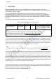
1. Overview Table 2: ESP32-WROOM-32E Specifications Categories Items Specifications Test Reliablity HTOL/HTSL/uHAST/TCT/ESD 802.11 b/g/n20/n40 Wi-Fi Protocols A-MPDU and A-MSDU aggregation and 0.4 s guard interval support Frequency range 2.412 GHz ~ 2.462GHz Protocols Bluetooth v4.
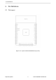
2. Pin Definitions 2. Pin Definitions 2.
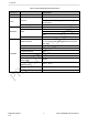
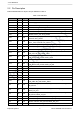
2. Pin Definitions 2.2 Pin Description ESP32-WROOM-32E has 38 pins. See pin definitions in Table 3. Table 3: Pin Definitions Name GND No. 1 Type P Function Ground 3V3 2 P Power supply EN 3 I Module-enable signal. Active high. SENSOR_VP 4 I GPIO36, ADC1_CH0, RTC_GPIO0 SENSOR_VN 5 I GPIO39, ADC1_CH3, RTC_GPIO3 IO34 6 I GPIO34, ADC1_CH6, RTC_GPIO4 IO35 7 I GPIO35, ADC1_CH7, RTC_GPIO5 IO32 8 I/O IO33 9 I/O IO25 Y R A GPIO32, XTAL_32K_P (32.
2. Pin Definitions Name IO19 No. 31 Type I/O Function GPIO19, VSPIQ, U0CTS, EMAC_TXD0 NC 32 - - IO21 33 I/O GPIO21, VSPIHD, EMAC_TX_EN RXD0 34 I/O GPIO3, U0RXD, CLK_OUT2 TXD0 35 I/O GPIO1, U0TXD, CLK_OUT3, EMAC_RXD2 IO22 36 I/O GPIO22, VSPIWP, U0RTS, EMAC_TXD1 IO23 37 I/O GPIO23, VSPID, HS1_STROBE GND 38 P Ground Notice: Y R A * GPIO6 to GPIO11 are connected to the SPI flash integrated on the module and are not connected out. N I M I L E R P 2.
2.
3. Functional Description 3. Functional Description This chapter describes the modules and functions integrated in ESP32-WROOM-32E. 3.1 CPU and Internal Memory ESP32-D0WD-V3 contains two low-power Xtensa® 32-bit LX6 microprocessors. The internal memory includes: • 448 KB of ROM for booting and core functions. • 520 KB of on-chip SRAM for data and instructions.
3. Functional Description 3.4 RTC and Low-Power Management With the use of advanced power-management technologies, ESP32 can switch between different power modes. For details on ESP32’s power consumption in different power modes, please refer to section ”RTC and LowPower Management” in ESP32 User Manual. N I M I L E R P Espressif Systems V0.
4. Peripherals and Sensors 4. Peripherals and Sensors Please refer to Section Peripherals and Sensors in ESP32 User Manual. Note: External connections can be made to any GPIO except for GPIOs in the range 6-11, 16, or 17. GPIOs 6-11 are connected to the module’s integrated SPI flash. For details, please see Section 6 Schematics.
5. Electrical Characteristics 5. Electrical Characteristics 5.1 Absolute Maximum Ratings Stresses beyond the absolute maximum ratings listed in the table below may cause permanent damage to the device. These are stress ratings only, and do not refer to the functional operation of the device that should follow the recommended operating conditions. Y R A Table 5: Absolute Maximum Ratings 1.
5. Electrical Characteristics Symbol I Parameter Min Typ Max Unit (VDD1 = 3.3 V, VOL = 0.495 V, output drive strength set to the maximum) - 28 - mA Resistance of internal pull-up resistor - 45 - kΩ Resistance of internal pull-down resistor - 45 - kΩ Low-level input voltage of CHIP_PU to power off the chip - - 0.6 V Low-level sink current OL R PU R PD V IL_nRST Notes: 1. Please see Appendix IO_MUX of ESP32 Datasheet for IO’s power domain.
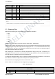
5. Electrical Characteristics 5.5 Bluetooth/BLE Radio 5.5.1 Receiver Table 9: Receiver Characteristics – Bluetooth/BLE Parameter Sensitivity @30.8% PER Conditions - Min - Typ –97 Max - Unit dBm Maximum received signal @30.8% PER - 0 - - dBm Co-channel C/I - - +10 - dB - –5 - dB - –5 - dB - –25 - dB - –35 - dB - –25 - dB - –45 - dB –10 - - dBm 2000 MHz ~ 2400 MHz –27 2500 MHz ~ 3000 MHz –27 - - dBm - - dBm 3000 MHz ~ 12.
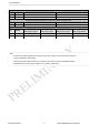
5. Electrical Characteristics Temperature ( ) 5.6 Reflow Profile Peak Temp. 235 ~ 250 250 Preheating zone 150 ~ 200 60 ~ 120s 217 200 Cooling zone Reflow zone !217 60 ~ 90s -1 ~ -5 /s Soldering time > 30s Ramp-up zone 1 ~ 3 /s 100 50 N I M I L E R P 25 0 0 50 100 150 Y R A Time (sec.) 200 250 Ramp-up zone — Temp.: <150 Time: 60 ~ 90s Ramp-up rate: 1 ~ 3 /s Preheating zone — Temp.: 150 ~ 200 Time: 60 ~ 120s Ramp-up rate: 0.3 ~ 0.8 /s Reflow zone — Temp.: >217 7LPH60 ~ 90s; Peak Temp.
6. Antenna Specifications 6 Antenna Specifications 6.1. 1 PCB Antenna Model: ESP ANT B Assembly: PTH Gain: 3.
6.
6.
6. Antenna Specifications Revision History be required as specified by 2.1093. Date Version Release notes 2020.02 V0.1 Preliminary release for certification CE& FCC OEM Guidance 1. Applicable FCC rules This module is granted by Single Modular Approval. It complies to the requirements of FCC part 15C, section 15.247 rules. 2. The specific operational use conditions This module can be used in IoT devices. The input voltage to the module is nominally 3.3V-3.6 V DC.
6. Antenna Antenna type: PCB antenna; Peak gain: 3.40dBi 7. Label and compliance information An exterior label on OEM’s end product can use wording such as the following: “Contains Transmitter Module FCC ID: 2A3DM-ESP32WROOM32E ” or “Contains FCC ID: 2A3DM-ESP32WROOM32E .” 8.
9. Additional testing, Part 15 Sub part B disclaimer The final host / module combination need to be evaluated against the FCC Part 15B criteria for unintentional radiators in order to be properly authorized for operation as a Part 15 digital device.