
User Manual

TM
Model 3000M0188-01
Rev. 5/12 6-47
KPM III Monitor Operation
PROGRAMMING/CONNECTING SEED TUBES, SHAFT
ROTATION SENSORS, AND/OR RADAR/MAGNETIC
DISTANCE SENSORS
NOTE: Sensor Setup screen automatically displays after
Planter Monitor is configured in Configure Planter Monitor
selection in Setup Mode screen.
IMPORTANT: All sensors MUST be unplugged before
programming begins.
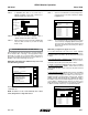
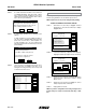
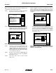
STEP 1 To access Mode Selection, press F6 key until Mode
Selection screen appears.
STEP 2 Select ‘‘1. Setup Mode’’ by turning rotary encoder
knob or press arrow keys. Press knob or Enter key
to display highlighted item.
STEP 3 Select ‘‘9. Sensor Setup’’ by turning knob or using
arrow keys. Press knob or Enter key to display
highlighted item.
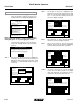
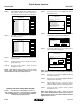
STEP 4 Attach planter harness to KPM III. Do NOT connect
any sensors to planter harness. With [Auto Detect]
selected press F1 key next to Install.
STEP 5 Plug in first pull row unit seed sensor (row 1),
working from left to right across planter. Connect
interplant unit sensors after all pull row unit sensors
have been connected following the same pattern.
When a sensor is connected to planter harness wait
for monitor to acknowledge sensor with two beeps.
NOTE: If monitor fails to acknowledge a sensor disconnect
sensor temporarily then reconnect sensor and wait for
monitor to acknowledge sensor with two beeps. If monitor
still fails to acknowledge sensor try connecting a different
sensor in this location.
Status
Plant
About
Setup Mode
Configuration:
Effective row spacing: 15.0
Front / Rear
1. General Settings
2. Seed Meter Settings
3. Row Unit Alarm Levels
4. Setup Data Logging
5. Configure Planter Monitor
6. Add New Muxbus Sensors
7. Add Single Interplant Row
8. Select Speed Sensor
9. Sensor Setup
10.Calibrate Speed Sensor
Logdata
Setup Mode
Install
Remove
Ignore
Revive
Done
Rear Row 1 OK
Rear Row 2 OK
Rear Row 3 OK
Rear Row 4 OK
Rear Row 5 OK
Rear Row 6 OK
Rear Row 7 OK
Rear Row 8 OK
Rear Row 9 OK
Rear Row 10 OK
Rear Row 11 OK
View
Sensor Setup
[Auto Detect]
[Seed Sensors]
Connect shaft rotation sensors or speed sensors
the same way seed sensors were connected,
making sure to work from left to right across planter.
(If applicable) plug in SDS, vacuum or PDP
(pneumatic down pressure) sensors the same way
seed sensors were connected.
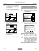
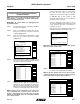
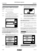
Progress is displayed on LCD screen as sensors
are connected. Example below indicates last seed
sensor found was Rear Row 4 and monitor is
looking for next sensor.
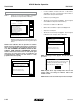
When all sensors are installed press F6 key to end
installation and return to “Setup Mode” screen.
NOTE: After each sensor has been installed ‘‘OK’’ appears
after sensor name on LCD screen.
Setup Mode
Done
[Auto Detect]
Rear Row 1 OK
Rear Row 2 OK
Rear Row 3 OK
Rear Row 4 OK
Rear Row 5 OK
Rear Row 6 OK
Rear Row 7 OK
Rear Row 8 OK
Rear Row 9 OK
Rear Row 10 OK
Rear Row 11 OK
Sensor Setup
[Auto Detect]
[Seed Sensors]
Auto Learn Mode
[Auto Detect]
Found Rear Row 4
Looking for next...
Plug in sensors one at a time,
any kind, but do same type
in order 1, 2, 3,...
Done press to end Auto Learn Mode
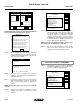
STEP 6 When ‘‘OK’’ appears behind ALL sensors, press F6
key next to Done. ‘Setup Mode’’ menu displays.
NOTE: If ‘‘OK slow’’ appears after a sensor, sensor is able to
communicate but at a slower speed. For system to run at top
speed of 9600 baud slow sensor must be replaced.
Setup Mode
Install
Remove
Ignore
Revive
Done
Rear Row 1 OK
Rear Row 2 OK
Rear Row 3 OK
Rear Row 4 OK
Rear Row 5 OK
Rear Row 6 OK
Rear Row 7 OK
Rear Row 8 OK
Rear Row 9 OK
Rear Row 10 OK
Rear Row 11 OK
View
Sensor Setup
[Auto Detect]
[Seed Sensors]
Setup Mode
Install
Remove
Ignore
Revive
Done
Rear Row 2 OK
Rear Row 3 OK
Rear Row 4 OK
Rear Row 5 OK
Rear Row 6 OK
Rear Row 7 OK
Rear Row 8 OK
Rear Row 9 OK
Rear Row 10 OK
Rear Row 11 OK
View
Sensor Setup
[Auto Detect]
[Seed Sensors]
Rear Row 1 OK