
User Manual


M0188-01Model 3000
TM
Machine Operation
2-14
Rev. 4/14
ROW MARKER ADJUSTMENTS
1. Multiply number of rows by the average row spacing in inches to determine total planting width.
NOTE: Refer to IS622 for Interplant option adjustments.
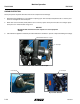
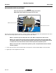
2. Lower planter and row marker assembly to ground.
3. Measure from planter center line to a point where blade contacts ground.
4. Adjust row marker extension so distance from marker disc blade to center line of planter is equal to total planting
width. Adjust right and left row marker assemblies equally and securely tighten clamping bolts.
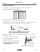
Row Marker Lengths
4 Row 30" 120" (304.8 cm)
4 Row 36" 144" (365.8 cm)
4 Row 38" 152" (386.1 cm)
6 Row 30" 180" (457.2 cm)
6 Row 36" 216" (548.6 cm)
6 Row 38" 228" (579.1 cm)
8 Row 30" 240" (609.6 cm)
NOTICE
Setting marker disc blade assembly at a sharper angle than needed
adds stress to row marker assembly and shortens bearing and
blade life. Set blade angle only as needed to leave a clear mark.
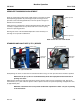
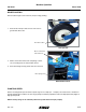
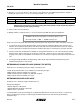
Marker disc blade is installed with concave side facing inward. Spindle assembly is slotted so hub and blade can be
angled to throw more or less dirt.
5. Loosen hardware and move assembly as required.
6. Tighten bolts to specified torque. See “Torque Values
Chart” in Maintenance Section.
7. Do a field test to ensure markers are properly adjusted.
NOTE: A notched marker blade is available from
Kinze through your Kinze Dealer for use in more
severe no till conditions.
Loosen hardware to
adjust blade angle.
Concave side faces
towards planter.
Row marker disc blade angle adjustment
Planter
centerline
Row marker adjustment distance