OPERATOR’S MANUAL M0245-01 MODEL 3140 STACK FOLD PLANTER Rev.
MODEL 3140 STACK FOLD PLANTER OPERATOR’S MANUAL M0245-01 Rev.
This page left blank intentionally.
M0245-01 Predelivery/Delivery Checklist Model 3140 TO THE DEALER Predelivery service includes assembly, lubrication, adjustment, and test. This service makes sure planter is delivered to the retail customer/end user ready for field use. PREDELIVERY CHECKLIST Use the following checklist and inspect planter after it is completely assembled. Check off each item found satisfactory or after proper adjustment is made. Row units properly spaced and optional attachments correctly assembled.
Model 3140 Predelivery/Delivery Checklist M0245-01 DELIVERY CHECKLIST Use the following checklist at time planter is delivered as a reminder of very important information which should be conveyed to retail customer/end user. Check off each item as it is fully explained. Check for proper operation of vacuum fan (If applicable) with tractor to be used with planter. Life expectancy of this or any other machine is dependent on regular lubrication as directed in the Operator Manual.
M0245-01 Table of Contents Machine Operation Model 3140 Brush-Type Seed Meter . . . . . . . . . . . . . . . . . . . . . . . . . . . 3-6 Initial Preparation of the Planter. . . . . . . . . . . . . . . . . . . . . 2-1 Finger Pickup Seed Meter . . . . . . . . . . . . . . . . . . . . . . . . . 3-7 Tractor Requirements. . . . . . . . . . . . . . . . . . . . . . . . . . . . . 2-2 EdgeVac Seed Meters. . . . . . . . . . . . . . . . . . . . . . . . . . . . 3-8 Tractor Preparation and Hookup . . . . . . . .
Model 3140 Table of Contents M0245-01 Seed Tube Guard/Inner Scraper . . . . . . . . . . . . . . . . . . . 6-17 Frame Mounted Coulter . . . . . . . . . . . . . . . . . . . . . . . . . 6-17 Residue Wheels (For Use With Frame Mounted Coulter). . . . . . . . . . . . . . . . . . . . . . . 6-17 Row Unit Mounted Disc Furrower . . . . . . . . . . . . . . . . . . 6-18 Row Unit Mounted Bed Leveler . . . . . . . . . . . . . . . . . . . . 6-18 Row Unit Mounted No Till Coulter. . . . . . . . . . . . . . . . . .
To the Owner M0245-01 Model 3140 Kinze Manufacturing, Inc. would like to thank you for your patronage. We appreciate your confidence in Kinze farm machinery. Your Kinze planter has been carefully designed to provide dependable operation in return for your investment. This manual has been prepared to aid you in planter operation and maintenance. It should be considered a permanent part of the machine and remain with the machine when you sell it.
Model 3140 Warranty M0245-01 The Kinze Limited Warranty for your new machine is stated on the retail purchaser’s copy of the Warranty And Delivery Receipt form. Additional copies of the Limited Warranty can be obtained through your Kinze Dealer. Warranty, within the warranty period, is provided as part of Kinze’s support program for registered Kinze products which have been operated and maintained as described in this manual.
Specifications M0245-01 Model 3140 GENERAL INFORMATION The Model 3110 Mounted Planter is available with EdgeVac or mechanical meters, conventional hoppers, and various other options. Contact your Kinze dealer for additional options which may be available for your specific model year planter. Information in this manual was current at time of printing. However, due to Kinze’s ongoing product improvement, production changes may cause your machine to appear slightly different in detail.
Specifications Model 3140 M0245-01 Tractor Hydraulic Requirements - Mechanical Configuration Requirements Base machine with mechanical meters 1 SCV 10 gpm Base machine with mechanical meters and optional row marker package 2 SCV 20 gpm Base machine with mechanical meters, optional row markers and dual lift assist package Base machine with mechanical meters, optional row markers, dual lift assist package, and wing down flex package Description #1 SCV: Planter fold #1 SCV: Planter fold #2 SCV: Row
M0245-01 General Safety Rules 1. Read and understand instructions provided in this manual and warning labels. Review these instructions frequently! 2. This machine is designed and built with your safety in mind. Do not make any alterations or changes to this machine. Any alteration to design or construction may create safety hazards. 3. A large portion of farm accidents happen from fatigue or carelessness. Safe and careful operation of tractor and planter will help prevent accidents. 4.
Model 3140 Safety Instructions, Signs, and Decals M0245-01 Following are some common hazard warnings associated with this equipment. Pay close attention to all safety, operating, and maintenance information in this manual and decals applied to your equipment. DANGER! Contacting or coming close to power lines or other high energy sources will cause death or serious injury. Keep away from power lines or high energy sources at all times.
M0245-01 Machine Operation Model 3140 The following information is general in nature and was written to aid the operator in preparation of the tractor and planter for use, and to provide general operating procedures. The operator's experience, familiarity with the machine and the following information should combine for efficient planter operation and good working habits. NOTICE Always raise the planter out of the ground when making sharp turns or backing up.
Model 3140 Machine Operation M0245-01 Tractor Requirements Approximate minimum tractor horsepower (HP) required for field work is listed below: 12 Row Narrow - 150 HP And Up 12 Row Wide And 16 Row Narrow - 180 HP And Up NOTE: Tractor must have adequate 3 point hitch lift capacity to lift weight of machine, attachments, seed and dry chemicals. Shipping weights do not include seed, dry chemicals or additional optional attachments. Tractor front end stability is necessary for safe and efficient operation.
Machine Operation M0245-01 Model 3140 3. Back tractor up to planter. Position lower hitch pins and bushings as shown in the following diagrams for your type of tractor hitch. Line up holes and insert hitch pins and lock in place with pins provided. It may be necessary to change the length of the upper link with the adjusting handle.
Model 3140 Machine Operation M0245-01 4. The planter is equipped with safety/warning lights which should be used whenever the planter is being transported. The connector is a 7 terminal breakaway connector conforming to ASAE standards. If your tractor is not equipped for safety/warning lights, check with your tractor dealer. EdgeVac Connect harness on planter to digital vacuum gauge console on tractor. Connect power lead from digital vacuum gauge console to power source.
M0245-01 Machine Operation Model 3140 6. With planter on a level surface, raise the planter slowly and watch for any interference. When raising a planter equipped with dual lift assist wheels, the front of the planter should raise and then the back using the lift assist wheels to raise the rear of the planter. When lowering the planter, the lift assist wheels should begin to lower the rear of the planter before lowering the front of the planter.
Machine Operation Model 3140 M0245-01 Leveling the Planter For proper performance of the planter and row units, it is important that the planter frame and row unit parallel arms operate approximately level. The toolbar should operate at a 20" to 22" height, measured from the planting surface to the bottom of the toolbar. When operating the planter, make sure the right and left lower link arms on the tractor are adjusted equally before attaching the planter.
M0245-01 Machine Operation Model 3140 Parking Stand Adjustment EdgeVac Shown Two parking stands, located on the front side of the main frame, are standard on all Model 3140 planters. The stands must be positioned so they are not directly behind the tractor tire or they will interfere when the planter is raised. Each parking stand has six positioning holes. By using these positioning holes, you can set the main frame parking height from 19" to 25".
Model 3140 Machine Operation M0245-01 Seed Rate Transmission Adjustment Planting population rate changes are made at the seed rate transmissions. The seed rate transmissions are designed to allow simple, rapid changes of sprockets to obtain the desired planting population. By removing the lynch pins on the hexagon shafts, sprockets can be interchanged with those from the sprocket storage rod bolted near each transmission. Chain tension is controlled by spring-loaded, dual-sprocket idlers.
Machine Operation M0245-01 Model 3140 Contact Wheel Drive Sprockets Drive Sprocket NOTE: 15 tooth, 19 tooth or 30 tooth drive sprockets at each contact drive wheel can be interchanged from the sprocket storage rod bolted near each transmission. The 15 and 19 tooth sprockets require use of a 218 pitch No. 40 chain. The 30 tooth sprocket requires use of a 224 pitch No. 40 chain. Chain tension is controlled by a spring-loaded sprocket idler.
Model 3140 Machine Operation M0245-01 Shear Protection 3/16" Shear Pin Transmission Shaft The planter driveline and seed and granular chemical drivelines are protected from damage by shear pins. If excessive load should cause a pin to shear, it is important to determine where binding has occurred before replacing the pin. Replace shear pins with same size and type. To prevent future binding or breakage of components, check driveline alignment and follow prescribed lubrication schedules.
M0245-01 Machine Operation Model 3140 Digital Vacuum Gauge Operation The digital vacuum gauge console is equipped with an ONOFF-ON type selector switch. The “FAN 1” setting should be used when the planter is equipped with one vacuum fan. NOTE: The toggle switch should be left in OFF position when the planter is not in use. If left in either fan position, the tractor battery will be drained.
Machine Operation Model 3140 M0245-01 Hydraulic Operation EdgeVac Seed Metering EdgeVac Seed Metering Wing Down Flex OR Dual Lift Assist Marker Wing Fold Wing Down Flex AND Dual Lift Assist Wing Fold Marker EdgeVac Planter may require up to four selective control valves (SCV).
M0245-01 Machine Operation Model 3140 Row Marker Hydraulic Operation WARNING! Always stand clear of marker assemblies and blades when planter is operating. DANGER To avoid serious injury or death, care must be taken when operating row markers around overhead power lines. The single valve marker system uses a sequencing valve which directs hydraulic flow to operate the markers alternately. Each time a marker is raised, the sequencing valve will direct flow to lower the opposite marker.
Machine Operation Model 3140 M0245-01 Row Marker Adjustments 1. Multiply number of rows by the average row spacing in inches to determine total planting width. Row Marker Lengths 12 Row 30" 360" (914.4 cm) 12 Row 36" 432" (1097.3 cm) 12 Row 38" 456" (1158.2 cm) 12 Row 40" 480" (1219.2 cm) 16 Row 30" 480" (1219.2 cm) 2. Lower planter and row marker assembly to ground. 3. Measure from planter center line to a point where blade contacts ground. 4.
Machine Operation M0245-01 Model 3140 Wing Flex Two hooks located over each wing hinge area can be positioned so toolbar (a) is locked rigid, (b) so planter wings have 8° up flex or (c) with Wing Down Flex Cylinder Package (See “Wing Down Flex Cylinder”) installed, so planter wings have 8° up flex and 8° down flex.
Machine Operation Model 3140 M0245-01 Wing Down Flex Cylinder ½" x 6" Cap Screw And Sleeve Hooks ⅝" x 6¾" Pin And Lynch Pins 1¼" x 11¼" Hinge Pin ¾" x 2½" Cap Screws Wing Down Flex Cylinder Installed To Allow 8° Up Flex And 8° Down Flex Hooks Positioned Over Hinge Pin For Transport To prevent the planter wings from sagging during transport should hydraulic pressure be lost, the hooks located over each hinge area should be repositioned prior to folding the planter.
Machine Operation M0245-01 Model 3140 Point Row Clutches With the use of electric-activated clutches, which disengage the drive, either half of the planter may be shut off for finishing up fields or for long point row situations. L.H. Side Of Planter Shown The selector switch for the clutches is located in the point row clutch control box which is installed on the tractor. NOTE: Switch should be left in OFF position when planter is not in use.
Model 3140 Machine Operation M0245-01 Two-Speed Point Row Clutches 1 2 3 1 2 3 Two-Speed Clutch Assembly 1 2 3 (-) (+) (-) Left Side Of Planter Viewed From Rear Of Planter Top View Of Control Box The optional Two-Speed Point Row Clutch Package is designed to allow on-the-go population rate adjustment as well as the capability to shut off either half of the planter for finishing up fields or for long point row situations.
Machine Operation M0245-01 Model 3140 Dual Lift Assist Wheels Dual lift assist wheel equipped machines require use of a quick hitch (customer-supplied) and the top link pin is not used. A single control valve operates the dual lift assist wheels. When raising a planter equipped with dual lift assist wheels, the front of the planter should raise and then the back using the lift assist wheels to raise the rear of the planter.
Model 3140 Machine Operation M0245-01 Piston Pump Mount/Drive Spring Adjustment Spring Tension Adjusting Bolt Adjust the pump drive tension springs by tightening the hex head adjustment bolts to maintain positive tire contact. The initial setting should result in a ⅛" gap between coils. Tighten jam nut against spring plug to hold setting. Jam Nut Initial Setting Approx.
M0245-01 Machine Operation Model 3140 Field Test Perform a field test with any change of field and/or planting conditions, seed size or planter adjustment to ensure proper seed placement and operation of row units. Check planter for front to rear and lateral level operation. See “Leveling the Planter”. Check all row units to be certain they are running level. Row unit parallel arms should be approximately parallel to the ground when planting. Check row markers for proper operation and adjustment.
Machine Operation Model 3140 M0245-01 3. Measure 1∕1000 of an acre. See chart for correct distance for row width being planted. For example, if planting 30" rows 1∕1000 of an acre would be 17' 5". 1∕1000 Acre Seed Population Count Row Width/Distance Row Width 15" 18" 19" 30" 36" Distance 34'10" 29'0" 27'8" 17'5" 14'6" 38" 13'10" NOTE: Seeds may bounce or roll when planting with closing wheels raised and planting depth set shallow affecting seed spacing accuracy. 4.
M0245-01 Machine Operation Model 3140 Determining Pounds Per Acre (Brush-Type Meter) Seeds per acre ÷ Seeds per pound (from label) = Pounds per acre If seeds per pound information is not available use the following averages: 2,600 seeds per pound for medium size soybeans 15,000 seeds per pound for medium size milo/grain sorghum 4,500 seeds per pound for medium size cotton Determining Bushels Per Acre Pounds per acre ÷ Seed unit weight = Bushels per acre Average Unit Weight of: 1 Bushel Soybeans = 60 Pou
Machine Operation Model 3140 M0245-01 Field Check Granular Chemical Application Temperature, humidity, speed, ground conditions, flowability of different material, or meter obstructions can affect granular chemical rate of delivery. WARNING Agricultural chemicals can cause death or serious injury to persons, animals, and plants or seriously damage soil, equipment, or property. Read and follow all chemical and equipment manufacturers labels and instructions.
Row Unit Operation M0245-01 Planting Depth Planting depth adjustment handle Planting depth is maintained by adjustable row unit gauge wheels. Depth adjustment range is approximately ½" to 3½". 1. Raise planter to remove weight from wheels. 2. Push down on depth adjustment handle and reposition it forward to decrease or rearward to increase planting depth. Initially adjust all units to the same setting. 3.
Row Unit Operation Model 3140 M0245-01 Drag Closing Attachment Drag closing attachment pulls loose soil over seed trench. NOTE: Use of a seed firming wheel or other seed firming device is recommended with drag closing attachment. Eccentric bushing Front and rear adjustment is made using slotted holes in blades. Adjust all rows the same. Wheel arm stop eccentric bushings provide lateral adjustment. Use a ¾" wrench to loosen closing wheel arm to wheel arm stop hardware.
M0245-01 Row Unit Operation Model 3140 Seed Hoppers Mechanical seed hopper has a capacity of 1.9 bushels. EdgeVac seed hopper has a capacity of 1.75 bushels. Use clean seed and make certain there are no foreign objects inside when filling seed hopper. Replace hopper lids after hoppers are filled to prevent accumulation of dust or dirt in seed meter which can cause premature wear. See “Finger Pickup Seed Meter” and/or “Brush-Type Seed Meter”.
Row Unit Operation Model 3140 M0245-01 Row Unit Chain Routing Row unit drive chains must be properly tensioned and aligned for proper operation and to minimize wear. Inspect and replace weak, worn or broken springs, idlers, and idler bushings. Direction of travel Closed end NOTE: Install connector link with closed end facing direction of travel. Mechanical Pull Row Unit Meter Drive NOTE: Reverse idler when worn on one side for extended use.
Row Unit Operation M0245-01 Model 3140 Quick Adjustable Down Force Springs Option (Standard or Heavy Duty) Standard and heavy duty quick adjustable down force springs are available in increase penetration in hard soil and keep row unit from bouncing in rough field conditions. Two springs per row, one on each side parallel arms, are used unless equipped with row unit mounted no till coulters. Row unit mounted no till coulters require four springs per row.
Row Unit Operation Model 3140 M0245-01 Brush-Type Seed Meter Crop Upper Disc Color-Code Brush Seed Size (Disc Part No.) Retainer Cells Range *Lubricant Soybean Black (GA5794) GD11122 60 2200 to 4000 seeds/lb. Graphite Talc Specialty Soybean Dark Blue (GA6184) GD11122 48 1400 to 2200 seeds/lb. Graphite Talc Small Milo/Grain Sorghum Red (GA5982) GD8237 30 14,000 to 20,000 seeds/lb. Talc Large Milo Grain Sorghum Light Blue (GA6187) GD8237 30 10,000 to 16,000 seeds/lb.
Row Unit Operation M0245-01 Model 3140 Turn seed disc counterclockwise when installing on meter hub while tightening two wing nuts that retain disc. Seed disc should have slight resistance when rotated counterclockwise after wing nuts are tight. Brush-type seed meter attaches to seed hopper same as finger pickup seed meter. Secure to bottom of seed hopper with two 5∕16" thumbscrews. Tighten thumbscrews slightly with pliers. DO NOT OVER TIGHTEN.
Row Unit Operation Model 3140 M0245-01 EdgeVac Seed Meters Crop Seed Size Range Singulator Brush Setting Vacuum Setting (H2O) 35-70 lbs./80k 5-7 18-20 Graphite Talc 4, 5 2210-4200 seeds/lb. 9 18 Graphite Talc 1, 4, 5 35-70 lbs./80k 5-7 18-20 Graphite Talc 4, 5 2210-4200 seeds/lb. 9 18 Graphite Talc 1, 4, 5 60 2200-4000 seeds/lb. 5 10 Graphite Talc 1 120 2200-4000 seeds/lb. 5 10 Graphite Talc - 60 10,000 - 20,000 seeds/lb.
M0245-01 Row Unit Operation Model 3140 NOTES: 1. Requires use of seed meter baffle. 2. Requires use of cleanout brush. 3. Requires use of cleanout brush w/ball-type ejector. 4. Flat seeds may require higher vacuum level. 5. Larger seeds may require lower singulator brush setting. Smaller seeds may require higher setting. NOTE: See “EdgeVac General Planting Rate Information” and “Check Seed Population” pages for more information.
Row Unit Operation Model 3140 M0245-01 w/Ball-Type Ejector Seed baffle NOTE: Damaged seed or seed containing foreign material will cause plugging of seed disc orifices and require more frequent seed meter cleanout to prevent underplanting. SEED BAFFLE Seed baffle prevents excessive seed in meter from restricting air flow though seed. Used with 60 Cell Milo/Grain Sorghum Disc, 60 Cell Soybean Disc, 120 Cell High-Rate Soybean Disc and 39 Cell, 24 Cell Popcorn Discs, and 80 Cell Sugar Beet Discs.
M0245-01 Row Unit Operation Model 3140 4. Adjust vacuum level to initial setting according to tables on page. NOTE: Vacuum reading will be much lower when seed disc cells are empty. Load all seed cells before setting vacuum level. NOTE: Operate vacuum fan 3-5 minutes to bring oil up to normal operating temperature prior to making final vacuum level adjustment. 5. Perform optional seed disc fill check.
Model 3140 Row Unit Operation M0245-01 Additives The use of graphite is recommended to promote seed flow, provide lubrication for the seed meter and to help dissipate static charge buildup. Among the available dry seed lubricants graphite is the most effective and easiest to use and it requires no mechanical agitation Lubricant Application Rate Graphite Conventional Hoppers 1 Tbs./Hopper Fill Talc Conventional Hoppers ¼ C.* *Double amount of talc for sunflowers.
Row Unit Operation M0245-01 Frame Mounted Coulter (Pull Row) Model 3140 Spring adjustment bolt Frame mounted coulters with 1" bubbled, 1" fluted (8 flutes) or ¾" fluted (13 flutes) blades are used on pull row units only. Spring anchor bar Springs provide down pressure on coulter for maximum penetration while exerting less shock load on row unit. Initial coulter blade location is in top hole. Relocate blade to one of lower two holes (1" increments) as wear occurs or for deeper blade operation.
Model 3140 Row Unit Operation M0245-01 Row Unit Mounted Disc Furrower (Pull Row) Disc furrowers are used to clear crop residue, dirt clods, and dry soil from in front of row units for a clean and smooth seed bed. The disc furrower may be equipped with 12" solid blades or 12" notched blades. Notched blades are for heavier residue conditions and cut crop residue and move it aside to prevent plugging or pushing.
Row Unit Operation M0245-01 Model 3140 Row Unit Mounted Residue Wheel Row unit mounted residue wheels are used on pull and push row units. Row Unit Mounted Residue Wheel Two adjustable springs on each residue wheel parallel links provide down force adjustment. Position 1 provides minimum down pressure and position 3 maximum down pressure. Position 2 Position 1 (Least) Position 3 (Most) Additional uplift or float Raise row unit and reposition springs to adjust down pressure.
Row Unit Operation Model 3140 M0245-01 Row Unit Mounted No Till Coulter Row unit mounted no till coulters with 1" bubbled, 1" fluted (8 flutes) or ¾" fluted (13 flutes) blades may be used on pull row units and push row units (¾" fluted shown). Four quick adjustable down force springs are required per row when using row unit mounted no till coulters. See “Quick Adjustable Down Force Springs Options”. Align coulter blade to row unit double disc openers.
Row Unit Operation M0245-01 Model 3140 Granular Chemical Hopper and Drive WARNING Agricultural chemicals can cause death or serious injury to persons, animals, and plants or seriously damage soil, equipment, or property. Read and follow all chemical and equipment manufacturers labels and instructions. The granular chemical hopper has a 1.4 cubic feet capacity. Make sure no foreign objects get into hopper when it is being filled.
Row Unit Operation Model 3140 M0245-01 Granular Chemical Banding Options Granular chemical banding options allow 4½" slope-compensating banding, straight drop in-furrow placement or 14" rear banding. NOTE: Granular chemical rear bander is not compatible with covering discs/single press wheel option.
Rate Charts M0245-01 Model 3140 General Planting Rate Information These planting rate charts apply to Kinze Model 3140 planters. NOTICE Sprocket combinations in these charts are for average conditions. Changes in sprocket combinations may be required for desired planting population. ALWAYS MAKE FIELD CHECKS TO BE SURE YOU ARE PLANTING AT DESIRED RATE. NOTICE Seed additives added in the hopper may affect finger pickup seed meter performance and accelerate wear.
Rate Charts Model 3140 M0245-01 PLANTING RATES FOR FINGER PICKUP SEED METERS (STANDARD DRIVE) APPROXIMATE SEEDS/ACRE FOR VARIOUS ROW WIDTHS Transmission Sprocket 30" Rows 36" Rows 38" Rows 40" Rows Drive 16,186 16,785 17,431 18,090 18,128 18,760 18,883 19,481 19,704 20,261 21,104 21,898 22,022 22,709 22,850 23,583 23,697 23,802 23,853 24,526 24,608 24,684 24,755 25,548 25,592 25,633 25,671 25,707 26,659 27,646 27,684 27,770 27,818 28,709 28,791 28,977 29,795 29,858 29,991 30,136 31,102 31,295 32,271
Rate Charts M0245-01 Model 3140 PLANTING RATES FOR BRUSH-TYPE SEED METERS (STANDARD DRIVE) APPROXIMATE SEEDS/ACRE FOR VARIOUS ROW WIDTHS Transmission Sprockets Drive Driven 17 17 17 19 19 17 17 19 19 23 19 24 24 17 24 26 24 26 23 27 24 25 19 27 28 23 28 24 25 23 26 27 28 26 27 28 28 27 26 28 27 24 23 25 24 28 23 28 27 19 26 28 25 27 23 26 23 23 17 24 24 19 23 19 19 17 19 19 19 17 17 17 60 Cell Soybean or High-Rate Milo/Grain Sorghum 30" 36" 38" 40" Rows Rows Rows Rows 80,928 83,926 87,154 90,449 93,7
Rate Charts Model 3140 M0245-01 PLANTING RATES FOR BRUSH-TYPE SEED METERS (STANDARD DRIVE) APPROXIMATE SEEDS/ACRE FOR VARIOUS ROW WIDTHS Transmission Sprockets Drive Driven 17 17 17 19 19 17 17 19 19 23 19 24 24 17 24 26 24 26 23 27 24 25 19 27 28 23 28 24 25 23 26 27 28 26 27 28 28 27 26 28 27 24 23 25 24 28 23 28 27 19 26 28 25 27 23 26 23 23 17 24 24 19 23 19 19 17 19 19 19 17 17 17 36 Cell Acid-Delinted Large Cotton 30" Rows 36" Rows 38" Rows 40" Rows Average Seed Spacing In Inches 48,557 50,3
Rate Charts M0245-01 Model 3140 PLANTING RATES FOR BRUSH-TYPE SEED METERS (STANDARD DRIVE) APPROXIMATE HILLS/ACRE FOR VARIOUS ROW WIDTHS Due to variations in cotton seed size, meters equipped with 12 cell acid-delinted hill-drop cotton discs will plant from 3 to 6 seeds per cell. Select proper disc for seed size range to be planted. To determine planter transmission setting, determine desired hill spacing and select the transmission ratio closest to the hill spacing in inches on the chart.
Rate Charts Model 3140 M0245-01 PLANTING RATES FOR (EDGEVAC) CORN/POPCORN 39 CELL DISC 15 TOOTH CONTACT WHEEL DRIVE SPROCKET APPROXIMATE SEEDS/ACRE FOR VARIOUS ROW WIDTHS 30" Rows 36" Rows 38" Rows 40" Rows 23,207 24,066 24,992 25,992 26,301 27,075 27,275 28,252 28,324 29,395 29,457 30,484 30,685 31,656 32,019 32,923 34,199 34,294 35,584 35,786 36,902 37,131 38,223 38,506 38,759 39,854 40,225 41,514 41,587 41,772 43,319 44,924 44,985 45,203 46,652 46,785 47,086 48,416 48,734 48,970 50,539 50,853 52,4
Rate Charts M0245-01 Model 3140 PLANTING RATES FOR (EDGEVAC) CORN/POPCORN 39 CELL DISC 19 TOOTH CONTACT WHEEL DRIVE SPROCKET APPROXIMATE SEEDS/ACRE FOR VARIOUS ROW WIDTHS 30" Rows 36" Rows 38" Rows 40" Rows 29,395 30,484 31,656 32,923 33,315 34,294 34,549 35,786 35,877 37,234 37,312 38,613 38,867 40,098 40,557 41,702 43,319 43,440 45,073 45,328 46,742 47,032 48,416 48,774 49,095 50,481 50,952 52,585 52,676 52,911 54,871 56,903 56,982 57,257 59,092 59,261 59,643 61,327 61,730 62,028 64,016 64,414 66,4
Rate Charts Model 3140 M0245-01 PLANTING RATES FOR (EDGEVAC) LOW-RATE CORN/POPCORN 24 CELL DISC 15 TOOTH CONTACT WHEEL DRIVE SPROCKET APPROXIMATE SEEDS/ACRE FOR VARIOUS ROW WIDTHS 30" Rows 36" Rows 38" Rows 40" Rows 14,281 14,810 15,380 15,995 16,185 16,661 16,785 17,386 17,430 18,089 18,127 18,759 18,883 19,481 19,704 20,260 21,046 21,104 21,898 22,022 22,709 22,850 23,522 23,696 23,852 24,525 24,754 25,547 25,592 25,706 26,658 27,645 27,683 27,817 28,709 28,791 28,976 29,794 29,990 30,135 31,101 31
Rate Charts M0245-01 Model 3140 PLANTING RATES FOR (EDGEVAC) LOW-RATE CORN/POPCORN 24 CELL DISC 19 TOOTH CONTACT WHEEL DRIVE SPROCKET APPROXIMATE HILLS/ACRE FOR VARIOUS ROW WIDTHS 30" Rows 36" Rows 38" Rows 40" Rows 18,089 18,759 19,481 20,260 20,501 21,104 21,261 22,022 22,078 22,913 22,961 23,762 23,918 24,676 24,958 25,663 26,658 26,732 27,737 27,894 28,764 28,943 29,794 30,015 30,212 31,066 31,355 32,360 32,416 32,561 33,767 35,017 35,066 35,235 36,364 36,468 36,703 37,739 37,988 38,171 39,395 39
Rate Charts Model 3140 M0245-01 PLANTING RATES FOR (EDGEVAC) SOYBEAN AND MILO/GRAIN SORGHUM 60 CELL DISCS 15 TOOTH CONTACT WHEEL DRIVE SPROCKET APPROXIMATE SEEDS/ACRE FOR VARIOUS ROW WIDTHS 30" Rows 36" Rows 38" Rows 40" Rows 35,703 37,025 38,449 39,987 40,463 41,653 41,962 43,464 43,576 45,223 45,319 46,898 47,207 48,702 49,259 50,650 52,615 52,761 54,744 55,055 56,772 57,124 58,805 59,240 59,630 61,314 61,885 63,868 63,979 64,265 66,645 69,113 69,208 69,543 71,772 71,977 72,440 74,486 74,976 75,338
Rate Charts M0245-01 Model 3140 PLANTING RATES FOR (EDGEVAC) SOYBEAN AND MILO/GRAIN SORGHUM 60 CELL DISCS 19 TOOTH CONTACT WHEEL DRIVE SPROCKET APPROXIMATE SEEDS/ACRE FOR VARIOUS ROW WIDTHS 30" Rows 36" Rows 38" Rows 40" Rows 45,223 46,898 48,702 50,650 51,253 52,761 53,152 55,055 55,196 57,283 57,404 59,405 59,796 61,689 62,395 64,157 66,645 66,830 69,343 69,736 71,911 72,358 74,486 75,037 75,531 77,664 78,387 80,900 81,040 81,402 84,417 87,544 87,664 88,087 90,911 91,171 91,758 94,349 94,969 95,428
Rate Charts Model 3140 M0245-01 PLANTING RATES FOR (EDGEVAC) SOYBEAN 60 CELL DISC 30 TOOTH CONTACT WHEEL DRIVE SPROCKET APPROXIMATE SEEDS/ACRE FOR VARIOUS ROW WIDTHS 30" Rows 36" Rows 38" Rows 40" Rows 71,406 74,050 76,898 79,974 80,926 83,306 83,924 86,928 87,151 90,447 90,637 93,797 94,414 97,404 98,519 101,301 105,229 105,521 109,488 110,109 113,544 114,249 117,609 118,480 119,260 122,627 123,770 127,737 127,959 128,530 133,290 138,227 138,417 139,086 143,543 143,954 144,881 148,971 149,952 150,67
Rate Charts M0245-01 Model 3140 PLANTING RATES FOR (EDGEVAC) HIGH-RATE SOYBEAN 120 CELL DISC 15 TOOTH CONTACT WHEEL DRIVE SPROCKET APPROXIMATE SEEDS/ACRE FOR VARIOUS ROW WIDTHS 30" Rows 36" Rows 38" Rows 40" Rows 71,406 74,050 76,898 79,974 80,926 83,306 83,924 86,928 87,151 90,447 90,637 93,797 94,414 97,404 98,519 101,301 105,229 105,521 109,488 110,109 113,544 114,249 117,609 118,480 119,260 122,627 123,770 127,737 127,959 128,530 133,290 138,227 138,417 139,086 143,543 143,954 144,881 148,971 149
Rate Charts Model 3140 M0245-01 PLANTING RATES FOR (EDGEVAC) HIGH-RATE SOYBEAN 120 CELL DISC 19 TOOTH CONTACT WHEEL DRIVE SPROCKET APPROXIMATE SEEDS/ACRE FOR VARIOUS ROW WIDTHS 30" Rows 36" Rows 38" Rows 40" Rows 90,447 93,797 97,404 101,301 102,507 105,521 106,303 110,109 110,392 114,566 114,807 118,809 119,591 123,379 124,791 128,314 133,290 133,661 138,685 139,472 143,822 144,715 148,971 150,075 151,062 155,328 156,775 161,800 162,081 162,805 168,834 175,087 175,328 176,175 181,822 182,341 183,516
Rate Charts M0245-01 Model 3140 PLANTING RATES FOR (EDGEVAC) ACID-DELINTED HILL-DROP COTTON (3 SEEDS PER CELL), 20 CELL DISC 15 TOOTH CONTACT WHEEL DRIVE SPROCKET APPROXIMATE HILLS/ACRE FOR VARIOUS ROW WIDTHS 30" Rows 36" Rows 38" Rows 40" Rows 11,901 12,342 12,816 13,329 13,488 13,884 13,987 14,488 14,525 15,074 15,106 15,633 15,736 16,234 16,420 16,883 17,538 17,587 18,248 18,352 18,924 19,041 19,602 19,652 19,747 19,835 19,877 20,438 20,506 20,569 20,628 21,289 21,326 21,361 21,392 21,422 22,215 2
Rate Charts Model 3140 M0245-01 PLANTING RATES FOR (EDGEVAC) ACID-DELINTED HILL-DROP COTTON (3 SEEDS PER CELL), 20 CELL DISC 19 TOOTH CONTACT WHEEL DRIVE SPROCKET APPROXIMATE HILLS/ACRE FOR VARIOUS ROW WIDTHS 30" Rows 36" Rows 38" Rows 40" Rows 15,074 15,633 16,234 16,883 17,084 17,587 17,717 18,352 18,399 19,094 19,135 19,802 19,932 20,563 20,798 21,386 22,215 22,277 23,114 23,245 23,970 24,119 24,829 24,892 25,012 25,124 25,177 25,888 25,975 26,055 26,129 26,967 27,013 27,057 27,097 27,134 28,139 2
Rate Charts M0245-01 Model 3140 PLANTING RATES FOR (EDGEVAC) ACID-DELINTED COTTON/SMALL DRY EDIBLE BEAN 54 CELL DISC 15 TOOTH CONTACT WHEEL DRIVE SPROCKET APPROXIMATE SEEDS/ACRE FOR VARIOUS ROW WIDTHS 30" Rows 36" Rows 38" Rows 40" Rows 32,132 33,323 34,604 35,988 36,417 37,488 37,766 39,118 39,218 40,701 40,787 42,209 42,486 43,832 44,334 45,585 47,353 47,485 49,270 49,549 51,095 51,412 52,924 53,316 53,667 55,182 55,696 57,481 57,581 57,838 59,981 62,202 62,288 62,588 64,595 64,779 65,196 67,037 67
Rate Charts Model 3140 M0245-01 PLANTING RATES FOR (EDGEVAC) ACID-DELINTED COTTON/SMALL DRY EDIBLE BEAN 54 CELL DISC 19 TOOTH CONTACT WHEEL DRIVE SPROCKET APPROXIMATE SEEDS/ACRE FOR VARIOUS ROW WIDTHS 30" Rows 36" Rows 38" Rows 40" Rows 40,701 42,209 43,832 45,585 46,128 47,485 47,836 49,549 49,676 51,555 51,663 53,464 53,816 55,521 56,156 57,741 59,981 60,147 62,408 62,762 64,720 65,122 67,037 67,534 67,978 69,897 70,549 72,810 72,936 73,262 75,975 78,789 78,898 79,279 81,820 82,053 82,582 84,914 85
Rate Charts M0245-01 Model 3140 PLANTING RATES FOR (EDGEVAC) LARGE DRY EDIBLE BEAN 54 CELL DISC 15 TOOTH CONTACT WHEEL DRIVE SPROCKET APPROXIMATE SEEDS/ACRE FOR VARIOUS ROW WIDTHS 30" Rows 36" Rows 38" Rows 40" Rows 32,132 33,323 34,604 35,988 36,417 37,488 37,766 39,118 39,218 40,701 40,787 42,209 42,486 43,832 44,334 45,585 47,353 47,485 49,270 49,549 51,095 51,412 52,924 53,316 53,667 55,182 55,696 57,481 57,581 57,838 59,981 62,202 62,288 62,588 64,595 64,779 65,196 67,037 67,478 67,804 69,977 70
Rate Charts Model 3140 M0245-01 PLANTING RATES FOR (EDGEVAC) LARGE DRY EDIBLE BEAN 54 CELL DISC 19 TOOTH CONTACT WHEEL DRIVE SPROCKET APPROXIMATE SEEDS/ACRE FOR VARIOUS ROW WIDTHS 30" Rows 36" Rows 38" Rows 40" Rows 40,701 42,209 43,832 45,585 46,128 47,485 47,836 49,549 49,676 51,555 51,663 53,464 53,816 55,521 56,156 57,741 59,981 60,147 62,408 62,762 64,720 65,122 67,037 67,534 67,978 69,897 70,549 72,810 72,936 73,262 75,975 78,789 78,898 79,279 81,820 82,053 82,582 84,914 85,472 85,885 88,638 89
M0245-01 Rate Charts Model 3140 PLANTING RATES FOR (EDGEVAC) SUGAR BEETS 80 CELL DISC 22 TOOTH CONTACT WHEEL DRIVE SPROCKET APPROXIMATE SEEDS/ACRE FOR VARIOUS ROW WIDTHS Transmission Sprockets Recomm. Speed Average Seed 30" Rows Drive Driven Range (MPH) Spacing In Inches 47,608 15 28 4 to 6 4.4 49,370 15 27 4 to 6 4.2 51,270 15 26 4 to 6 4.1 53,321 15 25 4 to 6 3.9 53,955 17 28 4 to 6 3.9 55,543 15 24 4 to 6 3.8 55,953 17 27 4 to 6 3.8 57,957 15 23 4 to 6 3.6 58,105 17 26 4 to 6 3.
Model 3140 Rate Charts M0245-01 PLANTING RATES FOR (EDGEVAC) SUGAR BEETS 80 CELL DISC 15 TOOTH CONTACT WHEEL DRIVE SPROCKET/19 TOOTH REVERSER DRIVEN SPROCKETS APPROXIMATE SEEDS/ACRE FOR VARIOUS ROW WIDTHS Transmission Sprockets Recomm. Speed Average Seed 30" Rows Drive Driven Range (MPH) Spacing In Inches 22,006 15 28 4 to 6 9.5 22,821 15 27 4 to 6 9.2 23,699 15 26 4 to 6 8.9 24,647 15 25 4 to 6 8.4 24,940 17 28 4 to 6 8.3 25,674 15 24 4 to 6 8.1 25,863 17 27 4 to 6 8.1 26,790 15 23 4 to 6 7.
Rate Charts M0245-01 Model 3140 DRY INSECTICIDE APPLICATION RATE APPROXIMATE POUNDS/ACRE AT 5 MPH FOR VARIOUS ROW WIDTHS Meter Setting 30" Rows 10 11 12 13 14 15 16 17 18 19 20 21 22 23 24 25 26 27 28 29 30 4.9 5.4 6.1 6.9 7.7 8.5 9.6 10.7 11.4 13.1 14.2 15.5 16.4 17.2 18.8 20.9 23.0 24.1 25.4 27.8 29.6 5 6 7 8 9 10 11 12 13 14 15 16 17 18 19 20 21 22 23 24 25 2.9 4.9 5.3 6.3 7.8 8.9 10.2 11.2 12.6 14.1 15.5 17.5 19.4 21.8 24.3 25.7 27.6 29.6 32.0 34.4 36.9 36" Rows CLAY GRANULES 4.1 4.5 5.1 5.7 6.
Rate Charts Model 3140 M0245-01 DRY HERBICIDE APPLICATION RATES APPROXIMATE POUNDS/ACRE AT 5 MPH FOR VARIOUS ROW WIDTHS CLAY GRANULES Meter Setting 30" Rows 36" Rows 38" Rows 40" Rows 10 4.7 3.9 3.7 3.5 11 5.2 4.4 4.1 3.9 12 5.8 4.9 4.6 4.4 13 6.5 5.4 5.1 4.9 14 7.3 6.1 5.7 5.5 15 8.2 6.9 6.5 6.2 16 9.0 7.5 7.1 6.8 17 9.9 8.2 7.8 7.4 18 10.7 8.9 8.4 8.0 19 11.6 9.7 9.2 8.7 20 12.6 10.5 10.0 9.5 21 13.6 11.3 10.7 10.2 22 14.6 12.1 11.
M0245-01 KPM III Monitor Operation Model 3140 KPM III Electronic Seed MonItor Ver. 3.1 INTRODUCTION KINZE ESC ACK The KPM III electronic seed monitor system consists of: • A tractor mounted KPM III console powered by tractor 12 VDC battery receives and displays information from planter mounted sensors. • Seed tube and sensor installed in each planter row unit. • A magnetic distance sensor installed on planter or a radar distance sensor installed on tractor.
KPM III Monitor Operation Model 3140 Monitor Key Functions Push keys select or change operating mode, active displays, or the current configuration. Depending on operating mode or current display selected, some keys may not be active. Each valid key press is acknowledged by a short beep and an action is taken. If a key press has no action associated, it is considered invalid, and there is no feedback.
KPM III Monitor Operation M0245-01 Changing Volume, Contrast, and Backlighting with AV Key Alarm, volume, LCD screen contrast, and backlighting may be adjusted at any time, regardless of what is displayed on screen. STEP 1 STEP 2 Configuring Planter Monitor When the KPM III is powered on for the first time it will go directly into the Planter Configuration screen (STEP 4). Press AV key. Contrast adjustment dialog box Status appears in center of display.
KPM III Monitor Operation Model 3140 STEP 3 Select ‘‘5. Configure Planter Monitor’’ by turning the knob or using the arrow keys. Press the knob or the Enter key to display the highlighted item. STEP 5 NOTE: Press F2 key next to Plant any time Plant option is available to return to Planter Configuration screen. Press knob or Enter key to select “Rear Rows” field. A drop down number pad appears. Turn knob or use arrow keys to highlight correct value then press knob to select number.
KPM III Monitor Operation M0245-01 STEP 8 STEP 9 STEP 10 STEP 11 STEP 12 If applicable, turn knob or use arrow keys to advance to “Vacuum”. Press knob or Enter key and a drop down menu will appear. Select correct number of vacuum sensors by turning knob or using arrow keys. Confirm selection by pressing knob or Enter key.
KPM III Monitor Operation Model 3140 Seed Meter Settings STEP 1 STEP 3 Scroll to ‘‘2. Seed Meter Settings” by turning rotary encoder knob or using arrow keys. Press knob or Enter key to display highlighted item. Configuration: STEP 4 Seed Meter Settings Meter Type Status Setup Mode Vacuum Mechanical Mechanical 19 / Rear teeth Meter Sprocket Front Plant Soybeans Configuration: Vacuum Corn Crop Type 1. General Settings 2. Seed Meter Seeds perSettings rev 12 Logdata 3.
KPM III Monitor Operation M0245-01 STEP 9 (If Applicable) Turn knob or use arrow keys to highlight “Interplant”. Press knob or Enter key to display Interplant drop down menu.
KPM III Monitor Operation Model 3140 STEP 3 Data Logging Mode STEP 1 Scroll to ‘‘4. Setup Data Logging” by turning the rotary encoder knob or using the arrow keys. Press the knob or Enter key to display the highlighted item. Setup Mode Configuration: Front / Rear 1. General Settings 2. Seed Meter Settings 3. Row Unit Alarm Levels 4. Setup Data Logging 5. Configure Planter Monitor 6. Add New Muxbus Sensors 7. Add Single Interplant Row 8. Select Speed Sensor 9. Sensor Setup 10.
KPM III Monitor Operation M0245-01 STEP 7 STEP 8 Use knob or arrow keys to scroll to Temperature box. Press knob or Enter key to display drop down keyboard. Use keyboard to enter temperature then press Enter key. Use knob or arrow keys to scroll to Humidity box. Press knob or Enter key to display drop down keyboard. Use keyboard to enter humidity then press Enter key.
KPM III Monitor Operation Model 3140 Kinze Planter Configuration Front Rows 11 Speed Rear Rows 12 Vacuum 0 SDS 0 Shafts 2 Setup Mode Sensors Installed Planter Type There should be one sensor for each Row and each Shaft. Coil Pick-Up Configuration: Front / Rear 1. General Settings 2. Seed Meter Settings 3. Row Unit Alarm Levels 4. Setup Data Logging 5. Configure Planter Monitor 6. Add New Muxbus Sensors 7. Add Single Interplant Row 8. Select Speed Sensor 9. Sensor Setup 10.
KPM III Monitor Operation M0245-01 STEP 2 To confirm note below turn knob or use arrow keys to highlight “OK” button, then press knob or Enter key to confirm. If single Interplant row is not to be added select “Cancel” key and press knob or Enter key to cancel or press ESC key. Status Setup Mode Reprogramming Speed Sensor This setting must be specified when monitor is first configured. It must be reprogrammed to use an alternate speed sensor. NOTE: Speed sensors may not be changed while planting.
KPM III Monitor Operation Model 3140 STEP 6 Plug in Magnetic Distance Sensor (MDS) and press F1 key next to Install. Press knob or Enter key to save information. Sensor Setup screen will appear.
KPM III Monitor Operation M0245-01 Model 3140 Programming/Connecting Seed Tubes, Shaft Rotation Sensors, and/or Radar/Magnetic Distance Sensors Connect shaft rotation sensors or speed sensors the same way seed sensors were connected, making sure to work from left to right across planter. NOTE: Sensor Setup screen automatically displays after Planter Monitor is configured in Configure Planter Monitor selection in Setup Mode screen.
KPM III Monitor Operation Model 3140 Speed Sensor Calibration/Programming STEP 1 Turn knob or use arrow keys to highlight ‘’10. Calibrate Speed Sensor” and press knob or Enter key. Setup Mode Configuration: Front / Rear 1. General Settings 2. Seed Meter Settings 3. Row Unit Alarm Levels 4. Setup Data Logging 5. Configure Planter Monitor 6. Add New Muxbus Sensors 7. Add Single Interplant Row 8. Select Speed Sensor 9. Sensor Setup 10.
KPM III Monitor Operation M0245-01 When correct distance pulse count is known, calibration is not needed and the following steps may be used. STEP 1 Turn knob or use arrow keys to highlight ‘’10. Calibrate Speed Sensor” and press knob or Enter key Setup Mode Configuration: Front / Rear 1. General Settings 2. Seed Meter Settings 3. Row Unit Alarm Levels 4. Setup Data Logging 5. Configure Planter Monitor 6. Add New Muxbus Sensors 7. Add Single Interplant Row 8. Select Speed Sensor 9. Sensor Setup 10.
KPM III Monitor Operation Model 3140 STEP 5 Acre Count Mode NOTE: When a tractor is equipped with a radar distance sensor, accumulating area without a planter attached is possible. STEP 1 Install an “Acre Count Switch Kit”. STEP 2 Enter into “Acre Count Mode”. 0.00 Implement Width Total Area With monitor OFF, attach an Acre Count Switch Kit to Muxbus connector, then turn monitor “ON”. STEP 2 Press F6 key until Mode Selection screen appears.
KPM III Monitor Operation M0245-01 Model 3140 Test Mode Enabling/Disabling Interplant Rows To Enable or Disable Interplant STEP 1 Press F6 key until Mode Selection screen appears. STEP 1 Return to “Planter Configuration” screen by pressing F2 key next to “Plant”. STEP 2 STEP 2 Press F6 key until “Kinze Planter Monitor III” screen appears. Select ‘‘5. Test Mode’’ by turning rotary encoder knob or using arrow keys. Press knob or Enter key to display highlighted item.
KPM III Monitor Operation Model 3140 STEP 5 TEST MODE screen displays test run data (seed count) for each row. Start *** TEST MODE *** STEP 6 0 0 0 0 0 0 0 0 0 0 0 0 out out out out out out out out out out out out of of of of of of of of of of of of 0 0 0 0 0 0 0 0 0 0 0 0 Help 120 110 100 90 80 70 60 % 1 120 110 100 90 80 70 60 % 1 Done Begin test with tractor stopped. For EdgeVac planters, ensure vacuum is on and seed discs are full. STEP 7 Press F1 key next to Start and plant a test strip.
KPM III Monitor Operation M0245-01 ROW SPACING • Press F2 key next to Spacing to display seed spacing keys. “Average Spacing” will appear in bottom L.H. corner of display. RowPop 2 3 4 NOTE: Soybeans will not show Skips/Multiples. • Press F3 key next to Accuracy to display drop down menu. Select either “Skips/Multiples” or “Accuracy” 5 6 7 8 9 10 11 12 RowPop Accuracy Spacing 120 110 100 90 80 70 60 % 1 Area 2 3 4 6.
KPM III Monitor Operation Model 3140 M0245-01 Speed/Shaft Rotation Average Spacing Spacing 2 3 4 0 5 6 7 8 9 10 11 12 Accuracy Area 2 3 4 6.7 120 110 100 90 80 70 60 % 1 120 110 100 90 80 70 60 % 1 Avg Pop RowPop 5 6 7 8 AC1 120 110 100 90 80 70 60 % 1 120 110 100 90 80 70 60 % 1 9 10 11 12 Other 8.03 RowPop Spacing Spacing Choose Item to Display Shaft RPM Ground Speed Area Battery Vacuum Seed Delivery Shaft RPM Other 2 3 4 5 6 7 Downpressure 8 MPH 2 3 4 5 6 7 0.
KPM III Monitor Operation M0245-01 Row can be removed by pressing F2 key next to Remove. A box appears asking for confirmation to remove row. “OK” box is highlighted in box. Warnings and Alarms STEP 1 Seed Rate Alarm - A seed rate alarm is activated whenever row average seed population drops below threshold set for that row.
KPM III Monitor Operation Model 3140 STEP 3 Counting Sensors Not Communicatining With Monitor - If monitor detects a communication error between sensor and monitor, monitor beeps twice. NOTE: If a sensor has been ignored, sensor configuration screen displays as shown below. • Try to reestablish communication with sensor(s) by pressing F2. Avg Pop 0 MPH F2 STEP 4 0.0 Message below shows multiple sensors with lost contact.
KPM III Monitor Operation M0245-01 STEP 6 Add Interplant Row Error – Planter monitor configuration must contain an odd number of front rows before single Interplant row unit can be added. 0 If monitor has been configured, it will show Planter Configuration screen and attempt to communicate with seed sensors. Status Normal 2 3 4 5 6 120 110 100 90 80 70 60 % 1 120 110 100 90 80 70 60 % 1 Freeze 7 Average 2 3 4 5 6 7 Section 8 0.
KPM III Monitor Operation Model 3140 M0245-01 Area Management Enable Area Counter There are 42 area counters: Total Area, Field Area and Area Counters 1 through 40. Total Area is always active but may be cleared. If cleared, Field Area is also cleared. Field Area and Area Counters 1 through 40 may be cleared, started or stopped separate from each other. • Highlight desired ‘‘Area Counter’’ by turning rotary encoder knob or using arrow keys. • Press knob or Enter key.
KPM III Monitor Operation M0245-01 Model 3140 NOTE: If “Total area” is highlighted and F3 key next to Clear is pressed the following request for confirmation displays. Clear Total Area Area Confirm Management Area Counters STEP 1 Status Total Area and Field Area will be cleared! Total Area 31.3 K 488.37 Rename SelectArea and press OK to 31.3 cleare area counters. Field K both488.37 Area Counter 1 31.3 K 486.02 Select and press Cancel to retain the values Clear Area Counter 2 0.0 K 0.
KPM III Monitor Operation Model 3140 Clearing Field Area STEP 1 STEP 4 Display Plant screen to reset counter. Avg Pop Spacing 2 3 4 5 6 7 8 9 10 11 12 Accuracy Area 2 3 4 5 6 7 8 9 10 11 12 Other 30618 8.03 NOTE: If “Area” is not displayed next to F4, press F2 next to “Normal”. STEP 2 STEP 5 Press F4 key next to Area then press F4 key next to Clear. A dialog box displays requesting confirmation to clear. 1 Area Total AreaCounter 1 31.3 K0.0 488.37 Rename Field 488.
Lubrication and Maintenance M0245-01 Model 3140 Lubrication Following pages show locations of all lubrication points. Proper lubrication of moving parts helps ensure efficient operation of your Kinze planter and prolongs the life of friction producing parts. Lubrication Symbols Lubricate at frequency indicated with SAE multipurpose grease. Lubricate at frequency indicated with high quality SAE 10 weight oil or spray lubricant.
Model 3140 Lubrication and Maintenance M0245-01 Drive Chains Lubricate all transmission and drive chains daily with a high quality chain lubricant. Extreme operating conditions such as dirt, temperature, or speed may require more frequent lubrication. If a chain becomes stiff, it should be removed, soaked, and washed in solvent to loosen and remove dirt from joints. Soak chain in oil so lubricant can penetrate between rollers and bushings.
M0245-01 Lubrication and Maintenance Model 3140 Inner Wheel Module Drive Chains Bushings Lubricate bushings at frequency indicated. Check each bolt for proper torque. If bolt is loose, removed it and inspect bushing for cracks and wear. Replace bushing if necessary. Use only hardened flat washers. Replace damaged flat washers with proper part. Torque hardware to 130 ft-lb (176.2 N-m).
Model 3140 Lubrication and Maintenance M0245-01 Wheel Bearings All drive, transport, and marker hub wheel bearings should be repacked annually and checked for wear. 1. Raise wheel off ground. 2. Check for bearing endplay by moving wheel side to side. 3. Rotate wheel to check for bearing roughness. If bearings sound rough, remove hub and inspect bearings. NOTE: To repack wheel hubs, follow procedure outlined for wheel bearing replacement except bearings and bearing cups are reused.
M0245-01 Lubrication and Maintenance Model 3140 3. Center Hinge - 4 Zerks Per Hinge Area 6. Cam Follower - 1 Zerk Per Cam 7. U-Joint Assembly - 1 Zerk Per Assembly 4. Link Assembly - 4 Zerks Per Link 8. Seed Rate Transmission Assemblies - Zerk (Idler) 5.
Model 3140 Lubrication and Maintenance Frame mounted Coulter - 1 Per Arm Lift Assist Arm - 1 Zerk Per Arm M0245-01 Gauge wheel arms - 1 per arm (Seals in gauge wheel arm are installed with lip facing out to allow grease to purge dirt away from seal. Pump grease into arm until fresh grease appears between washers and arm.) (If Applicable) Row Unit Mounted No Till Coulter Hubs- 1 Zerk Per Hub (Pump grease into hub until grease comes out around the seals. Spin hub while filling with grease.
Lubrication and Maintenance M0245-01 Model 3140 Mounting Bolts and Hardware WARNING Parts separation can result in death, serious injury, and damage to property and equipment. Check all hardware is tight before operating planter the first time. Check all hardware again after first 50 hours of operation and beginning of each planting season. NOTICE Over-tightening hardware can reduce its shock load capacity and cause equipment failure.
Lubrication and Maintenance Model 3140 M0245-01 Tire Servicing WARNING Explosive separation of rim and tire parts can result in death or serious injury. Rim and tire servicing, improper use of rims and tires, or worn or improperly maintained tires can cause tire explosion. To prevent tire explosions: • Maintain proper tire pressure. Inflating a tire above or below the recommended pressure can cause tire damage. • Mount tires only by properly trained personnel using proper equipment.
Lubrication and Maintenance M0245-01 Model 3140 Finger Pickup Seed Meter Inspection/Adjustment Brush attachment screw Baffle attachment to meter. Finger tabs should contact carrier plate in this area. Finger tabs should raise in this area. Meter attachment to hopper. Removing meter and baffle Proper finger operation 1. Remove two thumbscrews and meter from seed hopper and remove three cap screws and baffle from meter assembly. 2.
Lubrication and Maintenance Model 3140 M0245-01 7. Check indentations on carrier plate for wear before installing finger holder on carrier plate. Excessive wear of carrier plate at indentations will cause over planting especially with small sizes of seed. Inspect carrier plate annually. Life expectancy should be 250-300 acres per row of operation under average conditions. 8. Install wave washer and adjusting nut with finger holder flush against carrier.
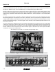
Lubrication and Maintenance M0245-01 Model 3140 Brush-Type Seed Meter Maintenance Meter housing Stainless steel wear band Seed disc Upper brush Lower brush Brush-type seed meter seed disc installed Upper brush retainer Brush-type seed meter parts Use clean, high quality seed. Damaged or cracked seed, hulls, or foreign materials can become lodged in upper brush and greatly reduce meter accuracy.
Model 3140 Lubrication and Maintenance M0245-01 UPPER BRUSH Upper brush Upper brush holds seed in seed disc pocket in seed retention area. Brush must apply enough pressure against seed in seed disc pocket as disc rotates through seed retention area to prevent seed from dropping out of disc pocket. A damaged spot, excessive brush wear, or foreign material lodged in brush may greatly reduce meter performance.
M0245-01 Lubrication and Maintenance Model 3140 EdgeVac Seed Meter Maintenance Singulator brush Air inlet screens Vacuum cover Crowder brush Wall brush Before each planting season inspect seed discs, singulator brush, crowder brush, wall brush, and air inlet screens and clean or replace as needed. Use clean, high quality seed for maximum meter accuracy. Damaged or cracked seed, hulls, and foreign material may become lodged in seed disc orifices and greatly reduce meter accuracy.
Model 3140 Lubrication and Maintenance M0245-01 Chain Tension Adjustment Drive chains have spring loaded idlers and are self-adjusting. Remove link to shorten chain if wear stretches chain and reduces spring tension. Check idler pivot points to make sure they rotate freely. See “Wrap Spring Wrench Assembly” in this section for additional information. Additional chain links are stored inside planter frame.
M0245-01 Lubrication and Maintenance Model 3140 Gauge Wheel Arm Bushing/Seal Replacement Gauge wheel arm bushings/seals Seal Seal Bushing Bushing NOTE: Gauge Wheel Arm Bushing and Seal Driver Kit (G1K296) is available through your Kinze Dealer. 1. Remove gauge wheel from arm. 2. Remove gauge wheel arm from shank assembly. 3. Remove seal and bushing and discard. Clean and dry inner bore. 4. Drive/press replacement bushing inside bore of arm to a depth of .125" below flush. 5.
Lubrication and Maintenance Model 3140 M0245-01 15" Seed Opener Disc Blade/Bearing Assembly NOTICE Excessive blade contact may result in premature disc opener bearing/hub failures and excessive wear on seed tube guard/inner scraper. When properly adjusted, if one blade is held in fixed position, opposite blade should rotate with less than 5 pounds force at outer edge of blade. Maintain approximately 1" ± ½" of blade-to-blade contact to properly open and form seed trench.
Lubrication and Maintenance M0245-01 Model 3140 Seed Tube Guard/Inner Scraper Seed tube guard protects seed tube and acts as inner scraper for seed opener disc blades. Remove seed tube and check for wear. Excessive wear on seed tube indicates a worn seed tube guard. Replace seed tube guard if it measures ⅝" or less at lower end. A new seed tube guard measures approximately ⅞".
Model 3140 Lubrication and Maintenance M0245-01 Row Unit Mounted Disc Furrower Lubricate bushings in support arm mounting bracket at frequency indicated in Lubrication of this section. Check each bolt for proper torque. If bolt is loose, it should be removed and bushing inspected for cracks and wear. Replace bushings as necessary. NOTE: Use only hardened flat washers. Replace damaged flat washers with proper part. Torque bolts to 130 ft-lb (176.2 N-m). Blade hubs are equipped with sealed bearings.
M0245-01 Lubrication and Maintenance Model 3140 Coulter Mounted Residue Wheels Wheel hubs are equipped with sealed bearings. If bearings sound or feel rough when wheel is rotated, replace them. Coulter mounted residue wheels Row Unit Mounted Residue Wheel Wheel hub is equipped with sealed bearings. If a bearing sounds or feels rough when wheel is rotated, replace them.
Lubrication and Maintenance Model 3140 M0245-01 Single and Two-Speed Point Row Clutch Maintenance Point row clutch is permanently lubricated and sealed and requires no periodic maintenance. Two-speed point row clutch is similar in design and operation to standard point row clutch except for two-speed function.
M0245-01 Lubrication and Maintenance Model 3140 The right hand clutch operates clockwise and the left hand clutch operates counterclockwise. Therefore, some of the parts of the clutch such as the wrap spring differ from one side of the planter to the other. Be sure to use the correct repair part if a clutch must be repaired. The control box is equipped with a resettable circuit breaker. To reset the circuit breaker, press the red button on the circuit breaker until it snaps into place.
Lubrication and Maintenance Model 3140 M0245-01 NOTICE Connect hydraulic motor case drain to a case drain return line with zero pressure on tractor or hydraulic motor will be damaged. DO NOT connect hydraulic motor case drain to SCV outlet. Contact tractor manufacturer for specific details on “zero pressure return”.
Lubrication and Maintenance M0245-01 Model 3140 Row Marker Sequencing/Flow Control Valve Inspection WARNING Pressurized hydraulic fluid can penetrate body tissue and result in death, serious infection, or other injuries. Fluid injected under skin must be IMMEDIATELY removed by a surgeon familiar with this type of injury. Make sure connections are tight and hoses and fittings are not damaged before applying system pressure. Leaks can be invisible. Keep away from suspected leaks.
Lubrication and Maintenance Model 3140 M0245-01 Row Marker Bearing Lubrication or Replacement Grease seal Outer cup Bearing Flat washer Hub Spindle Slotted hex nut Dust cap Inner cup Marker blade Hub shield Bearing Cotter pin Retainer 1. Remove retainer and marker blade. 2. Remove dust cap from hub. 2. Remove hub shield. Note direction of installation. 3. Remove cotter pin, slotted hex nut, and washer. 4. Slide hub from spindle. 5.
Lubrication and Maintenance M0245-01 Model 3140 Wheel Bearing Repack or Replacement Hub Jam nuts Bearing cup Inner bearing Outer bearing Spindle Bearing cup 1. Raise tire clear of ground and remove wheel. 2. Remove double jam nuts and slide hub from spindle. 3. Remove bearings and cups and discard if bearings are being replaced. Clean hub and dry. Remove bearings only and not cups if repacking. 4. Press in new bearing cups with thickest edge facing in. (Bearing replacement procedure only.
Model 3140 Lubrication and Maintenance M0245-01 Preparation for Storage Store planter in a dry sheltered area if possible. Remove all trash wrapped on sprockets or shafts and remove dirt that can draw and hold moisture. Clean all drive chains and coat with a rust preventative spray, or remove chains and submerge in oil. Lubricate planter and row units at all lubrication points. Inspect planter for parts that in need of replacement and order during “off” season.
Lubrication and Maintenance M0245-01 Model 3140 Electrical Wiring Diagram for Light Package A B C White MONITOR +12V Black MONITOR GROUND Green MONITOR DATA 3-Pin Connector A B C 3-Pin Connector * Optional customer-supplied auxiliary lights and wires may be wired into existing plug terminals. The light package supplied on the Model 3140 planter meets ASAE Standards. For the correct wiring harness to be wired into the lights on your tractor, check with the tractor manufacturer.
Lubrication and Maintenance Model 3140 M0245-01 Electrical Wiring Diagrams for Point Row Clutches 12 Amp Circuit Breaker CONTROL BOX ON TRACTOR 1 2 1 3 2 3 TRACTOR HARNESS Black Blue Orange Red (+) Black (-) Orange (-) Ground Blue (+) Red (+) (-) TO BATTERY * Red ** Blue * Red - R.H. Point Row Clutch ** Blue - L.H. Point Row Clutch PLANTER HARNESS TO BATTERY Black (-) Ground (-) Red (+) Black (-) Red (+) Red (+) Black (-) POINT ROW CLUTCH FOR R.H.
M0245-01 Lubrication and Maintenance Model 3140 Electrical Wiring Diagrams for Two-Speed Point Row Clutches CONTROL BOX ON TRACTOR 12 Amp Circuit Breaker Black Blue Orange Red TRACTOR HARNESS PLANTER HARNESS TO BATTERY Red - R.H. Point Row Clutch Solenoid (+) Blue - R.H. Reduced Rate Clutch Solenoid (+) Black - Ground (-) Orange/Red - L.H. Point Row Clutch Solenoid (+) Blue - L.H. Reduced Rate Clutch Solenoid (+) Black - Ground (-) Connects To Point Row Clutch Solenoids On L.H.
Lubrication and Maintenance Model 3140 M0245-01 CONTROL BOX ON TRACTOR 1 2 3 1 2 3 1 2 (-) 3 Orange/Red - L.H. Point Row Clutch (+) (-) TO BATTERY Red - R.H. Point Row Clutch Blue - Reduced Rate Clutch TWO-SPEED POINT ROW CLUTCH FOR L.H.
Lubrication and Maintenance M0245-01 Model 3140 Hydraulic Schematic - Vacuum Fan Motor System NOTICE Connect hydraulic motor case drain to a case drain return line with zero pressure on tractor or hydraulic motor will be damaged. DO NOT connect hydraulic motor case drain to SCV outlet. Contact tractor manufacturer for specific details on “zero pressure return”. Tractor Remote Valves ⅜" Hose (Case Drain) ½" Hose (Pressure) ¾" Hose (Return) Bulkhead Mount Check Valve Assembly (Located On R.H.
Lubrication and Maintenance Model 3140 M0245-01 Hydraulic Schematic - Fold System B Tractor Remote Valves A Bulkhead Mount Wing Fold Cylinder Wing Fold Cylinder Hydraulic Hydraulic Latch Latch B A Hydraulic Schematic - Row Marker System Bulkhead Mount A Row Marker Row Marker Cylinder Cylinder B Tractor Remote Valves Marker Sequencing/ Flow Contr
Lubrication and Maintenance M0245-01 Model 3140 Hydraulic Schematic - Dual Lift Assist Wheel Package B Accumulator A Bulkhead Mount 16 Row 30" Dual Lift Assist Cylinder Dual Lift Assist Cylinder Tractor Remote Valves B A Hydraulic Schematic - Dual Lift Assist Wheel Package (Plumbed Into 3 Point Circuit) A Accumulator Bulkhead Mount 3 Point Lift 16 Row 30" Dual Lift Assist Cylinder Dual Lift Assist Cylinder Flow Control Valve Installed with arrow pointed away from tractor.
Lubrication and Maintenance Model 3140 M0245-01 Hydraulic Schematic - Wing Down Flex Cylinder Package A B Bulkhead Mount Tractor Remote Valves B A Wing Down Flex Cylinder Wing Down Flex Cylinder Hydraulic Schematic - Wing Down Flex Cylinder Package and Dual Lift Assist Wheel Package Bulkhead Mount Markers Wing Fold Accumulator A Tractor Remote Valves B 16 Row 30" A B Wing Down Flex Cylinder Wing Down Flex Cylinder Dual Lift Assist Cylinder Dual Lift Assist Cylinder 6-34 9/12 TM
Troubleshooting M0245-01 Model 3140 Brush-Type Seed Meter PROBLEM Low count. POSSIBLE CAUSE Meter RPM too high. Misalignment between drive clutch and meter. Seed sensor not picking up all seeds dropped. SOLUTION Reduce planting speed. See “Seed Meter Drive Adjustment”. Clean seed tube. Switch meter to different row. If problem stays with same row, replace sensor. Lack of lubrication causing seeds not to Use graphite or talc as recommended. release from disc properly.
Model 3140 Troubleshooting M0245-01 EdgeVac Seed Meter PROBLEM Low seed count. Not planting seed. POSSIBLE CAUSE Meter RPM too high. Singulator brush setting too aggressive. Vacuum level too low. Seed sensor not picking up all seeds dropped. Seeds sticking to seed disc. Seed treatment buildup in seed disc recesses. Seed size too large for disc used. Wrong transmission setting. Wrong seed disc. Drive wheel slipage. SOLUTION Reduce planting rate or planting speed. Adjust singulator brush.
M0245-01 Troubleshooting Model 3140 EdgeVac Seed Meter PROBLEM High seed count. POSSIBLE CAUSE Wrong transmission setting. High vacuum. Wrong seed disc. Singulator brush setting not aggressive enough. Worn singulator brush. Seed leaking past wall brush. SOLUTION Change transmission to desired rate. Adjust vacuum level to appropriate level. Replace seed disc. Adjust singulator brush. Faulty vacuum gauge. Poor seed spacing. Obstruction in seed tube. Dirty/damaged seed disc. Wrong vacuum setting.
Troubleshooting Model 3140 M0245-01 Finger Pickup Seed Meter PROBLEM POSSIBLE CAUSE One row not planting seed. Drive release not engaged. Foreign material in hopper. Seed hopper empty. Row unit drive chain off of sprocket or broken. Unit is skipping. Foreign material or obstruction in meter. Finger holder improperly adjusted. SOLUTION Engage drive release mechanism. Clean hopper and finger carrier mechanism. Fill seed hopper. Check drive chain. Clean and inspect. Adjust to specifications. (22 to 25 in.
Troubleshooting M0245-01 Model 3140 KPM III Electronic Seed Monitor PROBLEM POSSIBLE CAUSE SOLUTION Single sensor communication alarm comes on. Faulty seed tube sensor. Replace sensor. Break in the harness just before the seed tube sensor. Inspect for break in harness and repair. If break can’t be found, replace harness section. Dirty or corroded connector. Clean connector. Faulty monitor. Repair/Replace monitor. Break in the harness just after the monitor.
Model 3140 Troubleshooting M0245-01 Point Row Clutch PROBLEM POSSIBLE CAUSE SOLUTION None of the clutches will disengage. Main fuse blown in control console. Replace defective fuse. Poor terminal connection in wiring harness. Repair or replace. Wiring damage in wiring harness. Repair or replace. Low voltage at coil. (12 volts required) Check battery connections. One section of planter will not reengage. Shear pin at seed drive transmission(s) sheared.
Troubleshooting M0245-01 Model 3140 Row Marker Operation PROBLEM POSSIBLE CAUSE SOLUTION Both markers lowering and only one raising at a time. Hoses from cylinders to valve connected backwards. Check to ensure proper hose routing. (See illustration below.) Same marker always operating. Spool in sequencing valve not shifting. Remove spool, inspect for foreign material, making sure all ports in spool are open. Clean and re-install.
This page left blank intentionally.
Kinze Manufacturing, Inc.