
Manual


M0241-01Model 3200
6-32 Rev. 7/12
TM
KPM III Monitor Operation
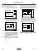
ADDING INTERPLANT ROWS
(REAR ROWS PREVIOUSLY PROGRAMMED ONLY)
NOTE: Planter monitor configuration must contain an odd
number of front rows before single Interplant
®
row unit can
be added.
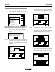
STEP 1 Highlight “6. Add New Muxbus Sensors” by turning
knob or using arrow keys. Press knob or Enter key
to display highlighted item.
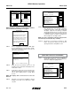
STEP 2 Note shown below displays. Highlight “OK” by
turning knob or using the arrow keys. Press knob or
Enter key to make selection.
NOTE: To prevent configuration from being changed, select
Cancel, then press the knob, Enter key or ESC key.
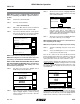
STEP 3 Turn knob or use arrow keys to highlight
“Front Rows” field and press knob or Enter
key. A drop down number pad appears.
STEP 4 Turn knob or use arrow keys to highlight first digit
of desired number and press knob to select the
number. For numbers containing more than one digit
select one digit at a time. The number will appear
in the “Front Rows” line. When correct number is
displayed on “Front Rows” line, press Enter key to
return to “Kinze Planter Configuration” screen.
NOTE: To prevent configuration from being changed select
Cancel, then press knob, Enter key or ESC key.
Status
Plant
About
Setup Mode
Configuration:
Effective row spacing: 15.0
Front / Rear
1. General Settings
2. Seed Meter Settings
3. Row Unit Alarm Levels
4. Setup Data Logging
5. Configure Planter Monitor
6. Add New Muxbus Sensors
7. Add Single Interplant Row
8. Select Speed Sensor
9. Sensor Setup
10.Calibrate Speed Sensor
Logdata
Warning
The planter monitor is already configured.
Select and press OK if you wish to change
the monitor configuration. You must then
learn each of the new sensors.
Select and press Cancel if you do not
wish to change the monitor configuration.
Cancel
OK
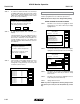
STEP 7 Use knob or arrow keys to scroll to Temperature
box. Press knob or Enter key to display drop down
keyboard. Use keyboard to enter temperature
then press Enter key.
STEP 8 Use knob or arrow keys to scroll to Humidity box.
Press knob or Enter key to display drop down
keyboard. Use keyboard to enter humidity then
press Enter key.
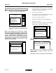
STEP 9 Use knob or arrow keys to scroll to the “OK” button
and press knob or Enter key. Display returns to
Setup Mode screen.
STEP 10 Press F2 key next to Plant to return to Planter
configuration screen.
STEP 11 Press F3 key next to “Logdata” to begin logging.
STEP 12 Press F3 key next to “Stoplog” to end logging.
Status
Plant
About
Setup Mode
Configuration:
Effective row spacing: 15.0
Front / Rear
1. General Settings
2. Seed Meter Settings
3. Row Unit Alarm Levels
4. Setup Data Logging
5. Configure Planter Monitor
6. Add New Muxbus Sensors
7. Add Single Interplant Row
8. Select Speed Sensor
9. Sensor Setup
10.Calibrate Speed Sensor
Logdata
Seed Data Logging
Cancel
OK
Destination
File Name
Log files are stored on USB drive in folder KPMIII_DataLogs
Names end with .999.csv (999 is a 3 digit sequence number)
Comment for file:
Temperature
Add new...
Humidity
0
Serial Port
Add new...
1 2 3
C
4 5 6
7 8 9
. 0
-
32
Status
Plant
About
Setup Mode
Configuration:
Effective row spacing: 15.0
Front / Rear
1. General Settings
2. Seed Meter Settings
3. Row Unit Alarm Levels
4. Setup Data Logging
5. Configure Planter Monitor
6. Add New Muxbus Sensors
7. Add Single Interplant Row
8. Select Speed Sensor
9. Sensor Setup
10.Calibrate Speed Sensor
Logdata
Seed Data Logging
Cancel
OK
Destination
File Name
Log files are stored on USB drive in folder KPMIII_DataLogs
Names end with .999.csv (999 is a 3 digit sequence number)
Comment for file:
Temperature
Add new...
Humidity
32
Serial Port
Add new...
1 2 3
C
4 5 6
7 8 9
. 0
-
0