
Manual


TM
Model 3200M0241-01
Rev. 7/12 6-33
KPM III Monitor Operation
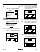
SDS = Seed Delivery System
There should be one sensor
for each Row and each Shaft.
Cancel
Kinze Planter Configuration
Planter Type Sensors Installed
Front Rows 11
OK
Rear Rows 12
Shafts 2
Speed Coil Pick-Up
Vacuum 0
SDS
Hydraulic Level/Temp
0
Downpressure Level
Status
Plant
About
Setup Mode
Configuration:
Effective row spacing: 15.0
Front / Rear
1. General Settings
2. Seed Meter Settings
3. Row Unit Alarm Levels
4. Setup Data Logging
5. Configure Planter Monitor
6. Add New Muxbus Sensors
7. Add Single Interplant Row
8. Select Speed Sensor
9. Sensor Setup
10.Calibrate Speed Sensor
Logdata
Note
Rear Rows may not be added via the
Add New Muxbus Sensors option.
Sensors may not be removed via the
Add New Muxbus Sensors option.
When adding front rows the number of
front rows must be equal to or one
less than the number of rear rows.
A single front row may not be added
via Add New Muxbus Sensors.
OK
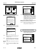
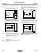
STEP 5 Sensor configuration screen displays. With “[Auto
Detect]” highlighted press F1 key next to “Install”.
Install sensors from left to right the same way rear
unit sensors were installed.
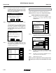
STEP 6 When all sensors are learned select F1 to end
installation. “Auto Learn Mode” box displays. Press
F6 key next to “Done”.
STEP 7 Scroll down to verify front rows are learned. Select
“OK” by pressing knob or Enter key. Press F6 key
next to “Done”. Display returns to “Setup Mode
Screen”.
NOTE: ‘‘OK’’ displays next to each sensor if no errors are
detected.
STEP 8 Turn knob or use arrow keys to highlight “1. General
Settings”. Press knob or use Enter key to make
selection.
Setup Mode
Done
Rear Row 1 OK
Rear Row 2 OK
Rear Row 3 OK
Rear Row 4 OK
Rear Row 5 OK
Rear Row 6 OK
Rear Row 7 OK
Rear Row 8 OK
Rear Row 9 OK
Rear Row 10 OK
Rear Row 11 OK
Sensor Setup
[Auto Detect]
[Seed Sensors]
Auto Learn Mode
Looking for first...
Plug in sensors one at a time,
any kind, but do same type
in order 1, 2, 3,...
Done press to end Auto Learn Mode
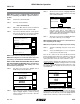
STEP 9 Turn the knob or use the arrow keys to highlight the
“Row Spacing” field. Press the knob or Enter key
to make the selection. A drop down number pad
will appear. Adjust the row spacing to Interplant
spacing by turning the knob or use the arrow keys
to highlight the correct value then press the knob
to select the number, for numbers containing more
than one digit select one digit at a time.
NOTE: To prevent configuration from being changed select
Cancel, then press knob, Enter key, or ESC key.
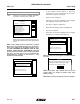
STEP 10 Turn knob or use arrow keys to advance to “OK”
button. Press knob or Enter key to save the row
spacing and return to “Setup Mode” screen.
Status
Plant
About
Setup Mode
Configuration:
Effective row spacing: 15.0
Front / Rear
1. General Settings
2. Seed Meter Settings
3. Row Unit Alarm Levels
4. Setup Data Logging
5. Configure Planter Monitor
6. Add New Muxbus Sensors
7. Add Single Interplant Row
8. Select Speed Sensor
9. Sensor Setup
10.Calibrate Speed Sensor
Logdata
ADDING EVEN-ROW PACKAGE
(FRONT ROWS PREVIOUSLY PROGRAMMED)
STEP 1 Turn the knob or use the arrow keys to highlight ‘‘7.
Add Single Interplant Row’’. Press the knob or the
Enter key to display the highlighted item.
Status
Plant
About
Setup Mode
Configuration:
Effective row spacing: 15.0
Front / Rear
1. General Settings
2. Seed Meter Settings
3. Row Unit Alarm Levels
4. Setup Data Logging
5. Configure Planter Monitor
6. Add New Muxbus Sensors
7. Add Single Interplant Row
8. Select Speed Sensor
9. Sensor Setup
10.Calibrate Speed Sensor
Logdata
NOTE: Attempting to add rear rows while adding new Muxbus
sensors will cause the following note to appear.