MODEL 4900 FRONT FOLD PLANTER OPERATOR MANUAL M0247-01 This manual is applicable to: Rev.
This page intentionally left blank.
M0247-01 Predelivery/Delivery Checklist Model 4900 TO THE DEALER Predelivery service includes assembly, lubrication, adjustment and test. This service helps ensure planter is delivered to retail customer/end user ready for field use. PREDELIVERY CHECKLIST Use the following checklist after planter is completely assembled. Check off each item as it is found satisfactory or after proper adjustment is made. Row units properly spaced and optional attachments correctly assembled.
Model 4900 Predelivery/Delivery Checklist M0247-01 DELIVERY CHECKLIST Use the following checklist at time planter is delivered as a reminder of very important information which should be conveyed to retail customer/end user. Check off each item as it is fully explained. Check proper operation of vacuum fan, bulk fill fan, and PTO-driven pump (If applicable) with tractor used with planter.
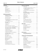
M0247-01 Table of Contents Overview Model 4900 Row Unit Operation To The Owner . . . . . . . . . . . . . . . . . . . . . . . . . . . . . . . . . . 1-1 Planting Depth . . . . . . . . . . . . . . . . . . . . . . . . . . . . . . . . . . 3-1 Warranty . . . . . . . . . . . . . . . . . . . . . . . . . . . . . . . . . . . . . . 1-2 “V” Closing Wheel Adjustment (Rubber or Cast Iron) . . . . 3-1 General Information . . . . . . . . . . . . . . . . . . . . . . . . . . . . . .
Model 4900 M0247-01 Gauge Wheel Adjustment . . . . . . . . . . . . . . . . . . . . . . . . 6-12 Insecticide Motor Cable . . . . . . . . . . . . . . . . . . . . . . . . . . 6-33 Gauge Wheel Arm Pivot Spindle Replacement . . . . . . . . 6-12 Insecticide Communication Cable. . . . . . . . . . . . . . . . . . 6-34 Gauge Wheel Arm Bushing/Seal Replacement . . . . . . . . 6-13 Motor Cable. . . . . . . . . . . . . . . . . . . . . . . . . . . . . . . . . . .
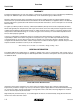
To The Owner Model 4900 M0247-01 Kinze Manufacturing, Inc. thanks you for your patronage. We appreciate your confidence in Kinze farm machinery. Your Kinze planter has been carefully designed to provide dependable operation in return for your investment. This manual has been prepared to aid you in the operation and maintenance of the planter. It should be considered a permanent part of the machine and remain with the machine when you sell it.
Model 4900 Overview M0247-01 Warranty The Kinze Limited Warranty for your new machine is stated on the retail purchaser’s copy of the Warranty And Delivery Receipt form. Additional copies of the Limited Warranty can be obtained through your Kinze Dealer. Warranty, within the warranty period, is provided as part of Kinze’s support program for registered Kinze products which have been operated and maintained as described in this manual.
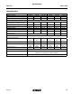
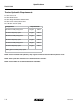
Specifications M0247-01 Model 4900 Specifications Specification Number of Rows Row Spacing Weight Empty (Vacuum Meter) Transport Height (with optional row marker package) Planting Height Planting Length Transport Length Planting Width Transport Width (14'-0" with granular chemical option) Seed Capacity Bulk Fill Dimensions (planting position height) Transport Tire Size (4) Transport Tire Pressure Wing Tires Field Tire Pressure Conventional Hoppers Bulk Fill 12R 30 16R 30 24R 30 12R 30 16R 30 30" 30" 30"
Specifications Model 4900 M0247-01 Tractor Hydraulic Requirements #1 SCV: Planter Lift #2 SCV: Markers/Fold #3 SCV: Weight Distribution/ASD/Fertilizer #4 SCV: Power Pack/Hydraulic Drive #5 & #6 SCV: Vacuum (PTO) Configuration Requirements* 24R without PTO pump option 54 gpm 6 SCV 24R with PTO pump option 37 gpm 4 SCV 16R without PTO pump option 47 gpm 6 SCV 16R with PTO pump option 37 gpm 4 SCV 12R without PTO pump option 46 gpm 6 SCV 12R with PTO pump option 37 gpm 4 SCV *Add 4 gpm f
M0247-01 General Safety Rules 1. Read and understand instructions provided in this manual and warning labels. Review these instructions frequently! 2. This machine is designed and built with your safety in mind. Do not make any alterations or changes to this machine. Any alteration to design or construction may create safety hazards. 3. A large portion of farm accidents happen from fatigue or carelessness. Safe and careful operation of tractor and planter will help prevent accidents. 4.
Safety Precautions Model 4900 M0247-01 Following are some common hazard warnings associated with this equipment. Pay close attention to all safety, operating, and maintenance information in this manual and decals applied to your equipment. DANGER! Contacting or coming close to power lines or other high energy sources will cause death or serious injury. Keep away from power lines or high energy sources at all times.
Machine Operation M0247-01 Model 4900 Row Marker Safety Lockup WARNING Row marker can lower at any time and could cause death or serious injury. Stay away from row markers! Install safety lockup device when not in use. Row Marker Safety Lockup Installed Row Marker Safety Lockup Stored Always install row marker lockups when working on, storing, or transporting planter. Hold in place with two clevis pins. 2-1 Rev.
Machine Operation Model 4900 M0247-01 WARNING Planter hitch may raise uncontrollably during folding/unfolding and can cause death, serious injury, or damage property and equipment. DO NOT fold or unfold planter without planter attached to a tractor. DO NOT unhitch planter from tractor unless fully folded for transport or fully unfolded with planting units lowered to ground.
Machine Operation M0247-01 Model 4900 WARNING Improperly operating or working on this equipment could result in death or serious injury. Read and follow all instructions in Operator Manual before operating or working on this equipment. Initial Planter Preparation Following information is general in nature to aid in preparation of tractor and planter for use, and to provide general operating procedures.
Machine Operation Model 4900 M0247-01 Tractor Requirements WARNING Loss of control of equipment during transport can result in death, serious injury, or damage to property and equipment. Tractor gross weight must be greater than planter gross weight with attachments and options. Consult your dealer for information on horsepower requirements and tractor compatibility. Requirements vary with planter options, tillage, and terrain.
M0247-01 Machine Operation Model 4900 Tractor Preparation and Hookup 1. Back tractor to planter and connect with minimum 1¼" diameter hitch pin or 2 point hitch. Make sure hitch pin is secured with a locking pin or cotter pin if tractor is not equipped with a hitch pin locking device or 2-point hitch. NOTE: DO NOT install safety chain using clevis mounting hardware. Safety chain MUST be installed separately. 2.
Machine Operation Model 4900 M0247-01 Color and Label Machine Function Hose Size Hose Function Red AA Field Lift ½" Pressure/Return ½" Pressure/Return ⅜" Pressure/Return ⅜" Pressure/Return 5/8 Return Black PP ½" Pressure Orange CD ⅜" Case Drain Bulk Fill System Pressure Fan (Hydraulic Weight Transfer) 5/8" Return ½" Pressure ⅜" Case Drain Vacuum Meter Fans 5/8" Return Green PP ½" Pressure Orange CD ⅜" Case Drain Red BB Blue AA Planter Fold & Row Marker Blue BB Blac
Machine Operation M0247-01 Model 4900 Transporting Planter WARNING Uncontrolled movement of equipment can cause loss of control and could result in death, serious injury, or damage to property and equipment. Install all safety pins before transporting equipment. WARNING Uncontrolled machine movement can crush or cause loss of control resulting in death, serious injury, or damage to property and equipment. Install all safety lockup devices before working under or transporting this equipment.
Machine Operation Model 4900 M0247-01 Level Planter Approximately parallel with planting surface Level Row Units Clevis Adjustment Holes Toolbar should operate at 23"-25" height from planting surface. Tire pressures must be maintained at pressures specified for planter to operate level laterally. Check toolbar and row unit parallel arms are level front to back with planter lowered to proper operating height. Five holes in the hitch bracket allow clevis to be raised or lowered.
M0247-01 Machine Operation Jump Start Sensor Model 4900 Jump start sensor The jump start sensor is intended to reduce the seed gap when starting from a stop with the planter in the ground. For the jump start sensor to work as intended, the planter speed sensor needs to be set within 1/8” of the pick-up disc. The planter speed sensor also needs to be calibrated properly. Refer to the ISOBUS manual for calibration instructions.
Machine Operation Model 4900 M0247-01 Transport to Field Sequence using isobus Position planter in a relatively flat open area without furrows, etc. SUMMARIZED TRANSPORT TO FIELD SEQUENCE USING ISOBUS VIRTUAL TERMINAL NOTICE Folding planter without using tractor to assist may cause equipment damage especially in soft conditions or when loaded with seed or fertilizer. Use tractor to reduce stress on frame, drive, and transport components. 1. 2. 3. 4. Lower transport axle to field turnaround position.
M0247-01 Machine Operation Model 4900 NOTICE DO NOT fold or unfold planter without planter attached to a tractor. DO NOT unhitch planter from tractor unless fully folded for transport or fully unfolded with planting units lowered to ground. 1. Remove and store locking pin on drawbar hitch. Install locking pin here for transport Locking pin storage Locking Pin for Drawbar Hitch 2-11 Rev.
Model 4900 Machine Operation M0247-01 2. Operate the proper hydraulic tractor control and press and hold the WING WHEEL LOWER button on your ISOBUS monitor to lower wing wheels into field turnaround position. 3. Operate the proper hydraulic tractor control and press and hold the ROTATE AXLE button on your ISOBUS monitor to lower transport axle to field turnaround position. If equipped with flip axle, move tires to field turnaround position as shown below.
M0247-01 4. Machine Operation Model 4900 For planters equipped with drawbar hitch, operate proper hydraulic tractor control and press and hold the LOWER HITCH button on your ISOBUS monitor to unhook wings. For planters equipped with 2-point hitch, operate proper hydraulic tractor control to lower drawbar to unhook wings. ISOBUS Monitor Unfold Screen Hitch Release from Wing Hook 2-13 Rev.
Machine Operation Model 4900 M0247-01 NOTICE Unfolding planter without using tractor to assist may cause equipment damage especially in soft conditions or when loaded with seed or fertilizer. Use tractor to reduce stress on frame, drive, and transport components. 5. Operate the proper hydraulic tractor control and press and hold the UNFOLD button on your ISOBUS monitor to move wings out, away from tractor.
M0247-01 Machine Operation 6. Lower drawbar or 2-point hitch to level machine during planting. 7. Lower planter and hold hydraulic lever for an additional 10-15 seconds to rephase cylinders. Model 4900 2-15 Rev.
Machine Operation Model 4900 M0247-01 Transport to Field Sequence USING CONTROL BOX Position planter in a relatively flat open area without furrows, etc. SUMMARIZED TRANSPORT TO FIELD SEQUENCE USING CONTROL BOX NOTICE Folding planter without using tractor to assist may cause equipment damage especially in soft conditions or when loaded with seed or fertilizer. Use tractor to reduce stress on frame, drive, and transport components.
M0247-01 Machine Operation Model 4900 NOTICE DO NOT fold or unfold planter without planter attached to a tractor. DO NOT unhitch planter from tractor unless fully folded for transport or fully unfolded with planting units lowered to ground. 1. Remove and store locking pin on drawbar hitch. Install locking pin here for transport Locking pin storage Locking Pin for Drawbar Hitch 2-17 Rev.
Model 4900 Machine Operation 2. Place FUNCTION switch on control box in fold position. M0247-01 LEFT 3. Operate the proper hydraulic tractor control and press and hold the WING WHEEL switch down to lower wing wheels into field turnaround position. 4. Operate the proper hydraulic tractor control and press and hold the AXLE switch up to lower transport axle to field turnaround position. If equipped with flip axle, move tires to field turnaround position as shown below.
M0247-01 5. Machine Operation For planters equipped with drawbar hitch, operate proper hydraulic tractor control and press and hold the HITCH button down to raise drawbar to unhook wings. For planters equipped with 2-point hitch, operate proper hydraulic tractor control to lower drawbar to unhook wings. Model 4900 FUNCTION MARKERS LEFT RIGHT PLANT OFF FOLD OFF AXLE FOLD OFF WING WHEELS HITCH MAIN 15 AMP TM Control Box Hitch Release from Wing Hook 2-19 Rev.
Machine Operation Model 4900 M0247-01 NOTICE Unfolding planter without using tractor to assist may cause equipment damage especially in soft conditions or when loaded with seed or fertilizer. Use tractor to reduce stress on frame, drive, and transport components. 6. Operate the proper hydraulic tractor control and press the FOLD switch up to move wings out, away from tractor. Planter is completely unfolded when stub wings are latched into the H-frame as shown in bottom photos.
M0247-01 Machine Operation 7. Lower drawbar or 2-point hitch to level machine during planting. 8. Lower planter and hold hydraulic lever for an additional 10-15 seconds to rephase cylinders. Model 4900 2-21 Rev.
Model 4900 Machine Operation M0247-01 Field to Transport Sequence USING ISOBUS Position planter in a relatively flat open area without furrows, etc. SUMMARIZED FIELD TO TRANSPORT SEQUENCE USING ISOBUS VIRTUAL TERMINAL NOTICE Folding planter without using tractor to assist may cause equipment damage especially in soft conditions or when loaded with seed or fertilizer. Use tractor to reduce stress on frame, drive, and transport components. 1. Place planter into field turnaround position. 2.
M0247-01 Machine Operation Model 4900 NOTICE DO NOT fold or unfold planter without planter attached to a tractor. DO NOT unhitch planter from tractor unless fully folded for transport or fully unfolded with planting units lowered to ground. 1. Operate proper hydraulic tractor control to raise planter into field turnaround position. 2-23 Rev.
Model 4900 2. Machine Operation M0247-01 For planters equipped with drawbar hitch, operate proper hydraulic tractor control and press and hold the RAISE HITCH button on your ISOBUS monitor to raise drawbar to level planter frame. For planters equipped with 2-point hitch, operate proper hydraulic tractor control to raise drawbar to level planter frame. ISOBUS Monitor Fold Screen 2-24 Rev.
Machine Operation M0247-01 Model 4900 NOTICE Folding planter without using tractor to assist may cause equipment damage especially in soft conditions or when loaded with seed or fertilizer. Use tractor to reduce stress on frame, drive, and transport components. 3. Operate the proper hydraulic tractor control and press and hold the FOLD button on your ISOBUS monitor until 2 hooks are over the top of the inner hitch. 4. Lift drawbar or 2-point hitch to lock wings into place after folding.
Model 4900 Machine Operation M0247-01 5. Operate the proper hydraulic tractor control and press and hold the ROTATE AXLE button on your ISOBUS monitor to raise transport axle to either transport height, or if equipped with flip axle, to the rest position as shown below. 6. Operate the proper hydraulic tractor control and press and hold the WING WHEEL LIFT button on your ISOBUS monitor to raise wing wheels into transport position.
M0247-01 Machine Operation 7. Install locking pin on drawbar. Model 4900 Install locking pin here for transport Locking pin storage Locking Pin for Drawbar Hitch 2-27 Rev.
Machine Operation Model 4900 M0247-01 Field to Transport Sequence Using Control Box Position planter in a relatively flat open area without furrows, etc. SUMMARIZED FIELD TO TRANSPORT SEQUENCE USING CONTROL BOX NOTICE Folding planter without using tractor to assist may cause equipment damage especially in soft conditions or when loaded with seed or fertilizer. Use tractor to reduce stress on frame, drive, and transport components.
M0247-01 Machine Operation Model 4900 NOTICE DO NOT fold or unfold planter without planter attached to a tractor. DO NOT unhitch planter from tractor unless fully folded for transport or fully unfolded with planting units lowered to ground. 1. Operate proper hydraulic tractor control to raise planter into field turnaround position. 2-29 Rev.
Model 4900 Machine Operation 2. Place FUNCTION switch on control box in fold position. 3. For planters equipped with drawbar hitch, operate proper hydraulic tractor control and press the HITCH switch down to raise drawbar to level planter frame. For planters equipped with 2-point hitch, operate proper hydraulic tractor control to raise drawbar to level planter frame.
Machine Operation M0247-01 Model 4900 NOTICE Folding planter without using tractor to assist may cause equipment damage especially in soft conditions or when loaded with seed or fertilizer. Use tractor to reduce stress on frame, drive, and transport components. 4. Operate the proper hydraulic tractor control and press the FOLD switch up until 2 hooks are over the top of the inner hitch. FUNCTION MARKERS LEFT RIGHT PLANT OFF 5. Lift drawbar or 2-point hitch to lock wings into place after folding.
Model 4900 Machine Operation 6. Operate the proper hydraulic tractor control and press the AXLE switch up to raise transport axle to either transport height, or if equipped with flip axle, to the rest position as shown below. 7. Operate the proper hydraulic tractor control and press the WING WHEELS switch down to raise wing wheels into transport position.
M0247-01 Machine Operation 8. Install locking pin on drawbar. Model 4900 Install locking pin here for transport Locking pin storage Locking Pin for Drawbar Hitch 2-33 Rev.
Machine Operation Model 4900 M0247-01 Row Marker Operation DANGER! Contacting or coming close to power lines or other high energy sources will cause death or serious injury. Keep away from power lines or high energy sources at all times. ISOBUS Screen Row Marker Solenoid Valves Two solenoid valves on valve block at rear L.H. side of center frame, and a three position selector switch on control console permit operator to lower or raise desired row marker.
M0247-01 Machine Operation Row Marker Speed Adjustment Model 4900 NOTICE Excessive row marker travel speed can damage row markers. Adjust flow controls before row markers are first used. Marker hydraulic system includes two flow control valves. One flow control valve sets lowering speed and one sets raising speed of both markers. Flow controls determine amount of oil flow restriction through valves, varying marker travel speed. Loosen jam nut and turn control clockwise, or IN to slow travel speed.
Model 4900 Machine Operation M0247-01 Row Marker Cable Adjustment WARNING Uncontrolled marker movement can cause death or serious injury. set marker switch OFF and shut off tractor prior to adjustment. NOTE: Operate two-fold or three-fold row markers with the tractor's hydraulic valve in float position. NOTE: A cable or chain may be used. For continuity, cable will be used in this manual. Third stage Cable adjustment is critical.
Machine Operation M0247-01 Model 4900 Row Marker Length And Disc Blade Adjustment 1. Multiply number of rows by the average row spacing in inches to determine total planting width. Row Marker Lengths 12 Row 30" 360" (914.4 cm) 16 Row 30" 480" (1,219.2 cm) 24 Row 30" 720" (1,828.8 cm) 2. Lower planter and row marker assembly to ground. 3. Measure from planter center line to a point where blade contacts ground. 4.
Machine Operation Model 4900 M0247-01 Vacuum Meter System Kinze vacuum meter seed metering system includes seed meters, seed discs, and an air system consisting of a hydraulic driven vacuum fan which draws air through manifolds, hoses, and seed meters on each row unit. WARNING Moving fan blades can cause amputation or severe injury. Never operate vacuum fan with cover removed.
Machine Operation M0247-01 Model 4900 Bulk Fill System WARNING Do not remove lid during machine operation. Contents are pressurized and could result in death, serious injuries or equipment damage. Review operator manual for proper filling procedure. CAUTION Seed flying out of disconnected delivery tube at high velocity can cause injury. Do not disconnect delivery tubes when system is operating. DANGER DO NOT ENTER. Hazardous conditions inside will result in death or serious injury.
Model 4900 Machine Operation M0247-01 Bulk fill Entrainer Access Wing nut 1. Shut down bulk fill system. 2. Loosen wing nut and turn retainer holding shutoff door in its storage location. Rubber plug 3. Remove rubber plug closest to area in entrainer needing attention. Retainer Shutoff door 4. Insert shutoff door into open slot and push into entrainer at a slight upward angle. Bulk Fill Entrainer (End View) 5.
Machine Operation M0247-01 Model 4900 Bulk Fill Tanks - Clean Out Chute hooks Cleanout Chute Storage Location Cleanout Chute Installed 1. Remove bulk fill tank cleanout chute from storage location under L.H. bulk fill tank. 2. Position tube of chute under entrainer and attach hooks on each end of entrainment assembly. 3. Open cleanout doors and empty tank. 4. Close all cleanout doors and return cleanout chute to storage location.
Model 4900 Machine Operation M0247-01 Monitor Seed Levels 1. Main screen displays information for left and right hoppers. 2. Select L or R for individual hopper status information. 3. Select BACK to return to main screen. 4. Press down arrow once or twice for GROSS screen to appear. This provides combined status information for both hoppers. 5. Press down arrow again to return to main screen. 2-42 Rev.
M0247-01 Machine Operation Model 4900 Master Module The Master Module is found on the planter and relays information to and takes inputs from the Virtual Terminal (VT). It also executes the manual and automatic rate control, and swath control commands. These functions are available with the Kinze ISOBUS product control package. Master Module Planter Master Module (PMM) (Bulk fill system shown) 2-43 Rev.
Model 4900 Machine Operation M0247-01 Field Test Perform a field test with any change of field and/or planting conditions, seed size or planter adjustment to ensure proper seed placement and operation of row units. Check planter for front to rear and lateral level operation. See “Level Planter” on page 2-8. Check all row units to be certain they are running level. Row unit parallel arms should be approximately parallel to the ground when planting.
Machine Operation M0247-01 Model 4900 3. Measure 1∕1000 of an acre. See chart for correct distance for row width being planted. For example, planting 30" rows 1∕1000 of an acre is 17' 5". 1∕1000 Acre Seed Population Count Row Width/Distance Distance 26'2" 17'5" NOTE: Seeds may bounce or roll when planting with closing wheels raised and planting depth set shallow affecting seed spacing accuracy. 4. Count seeds in measured distance. 5. Multiply number of seeds placed in 1∕1000 of an acre by 1000.
Machine Operation Model 4900 M0247-01 Field Check Granular Chemical Application Temperature, humidity, speed, ground conditions, flowability of different material, or meter obstructions can affect granular chemical rate of delivery. WARNING Agricultural chemicals can cause death or serious injury to persons, animals, and plants or seriously damage soil, equipment, or property. Read and follow all chemical and equipment manufacturers labels and instructions.
Row Unit Operation M0247-01 Planting Depth Planting depth adjustment handle Planting depth is maintained by adjustable row unit gauge wheels. Depth adjustment range is approximately ½" to 3½". 1. Raise planter to remove weight from wheels. 2. Push down on depth adjustment handle and reposition it forward to decrease or rearward to increase planting depth. Initially adjust all units to the same setting. 3. Lower planter and check operation and planting depth of all row units.
Model 4900 Row Unit Operation M0247-01 Covering Discs/Single Press Wheel Adjustment Adjusting bolt " 2½ Tab ½" Locking nut Press Wheel Down Force Adjustment Check operation of covering discs/single press wheels after adjusting planting depth. Initial press wheel down force spring setting is 2½" between mounting arm tab and locking nut. Loosen ½" locking nut and turn adjusting bolt in to increase down force or out to decrease down force. Tighten locking nut against spring plug.
M0247-01 Row Unit Operation Model 4900 Seed Hoppers Seed hoppers have a capacity option of 1.9 or 3.0 bushels. NOTE: Planters with the insecticide option are required to use only the 1.9 bushel hoppers. Use clean seed and make certain there are no foreign objects inside when filling seed hopper. Replace hopper lids after hoppers are filled to prevent accumulation of dust or dirt in seed meter which can cause premature wear.
Row Unit Operation Model 4900 M0247-01 Quick Adjustable Down Force Springs Option Standard and heavy duty quick adjustable down force springs are available in increase penetration in hard soil and keep row unit from bouncing in rough field conditions. Two springs per row, one on each side parallel arms, are used unless equipped with row unit mounted no till coulters. Row unit mounted no till coulters require four springs per row.
M0247-01 Row Unit Operation Model 4900 Pneumatic Down Pressure Row unit down pressure can be adjusted on-the-go as field conditions change. ISOBUS monitor adjusts pressure (Older models may have a digital readout). One planter-mounted 12 VDC air compressor with 3-gallon capacity air tank supplies air for the down pressure system. Row Unit Air Spring Packages include upper and lower air spring mounting castings for pull row units, 150 psi rated air springs, ⅜" O.D.
Model 4900 Row Unit Operation M0247-01 Field Operation NOTE: Adjust down pressure with planter lowered and row openers in ground for most accurate adjustment. Pressure can be adjusted using your ISOBUS monitor. Refer to the ISOBUS manual for more information. Pressure gauge Air Compressor ADJUST DOWN PRESSURE FROM CAB Use the ISOBUS monitor to adjust down pressure. Refer to your ISOBUS manual for more information.
Row Unit Operation M0247-01 Model 4900 Vacuum Settings Crop Corn (light blue) Disc Part No. Cells Seed Size Range Singulator Setting Vacuum Setting (H2O) 35-70 lbs./80k 2 18-20 *Lubricant Ejector Wheel Graphite Talc 1 row 5 punches B0678 40 Soybean (black) B0848 120 2200-4000 seeds/lb. 0 10-14 Graphite Talc 2 rows 6 punches Sugar Beet (dark orange) B0683 60 Pelletized 2 15 Graphite 1 row 6 punches Milo (dark orange) B0683 60 10,000 - 20,000 seeds/lb.
Row Unit Operation Model 4900 M0247-01 NOTE: See “Field Check Seed Population” on page 2-44 for more information. Always field check seed population to ensure planting rates are correct. NOTE: Singulator settings are marked from 0 - 3. NOTE: Mixing seed sizes and shapes affects meter performance. Use consistent seed size and shape. NOTE: Use 1 tablespoon powdered graphite with each hopper fill of seed.
Row Unit Operation M0247-01 Model 4900 Ejector NOTE: Damaged seed or seed containing foreign material will cause plugging of seed disc orifices and require more frequent seed meter cleanout to prevent underplanting. Wheel-Type Ejectors Wheel-type ejectors expel seed remants from seed disc orifices. These ejectors are disc specific and colored coded to match disc. NOTICE Replace hopper or tank lids after filling to prevent accumulation of dust or dirt in seed meter resulting in premature wear.
Model 4900 Row Unit Operation M0247-01 4. Adjust vacuum level to initial setting according to tables on page. NOTE: Vacuum reading will be much lower when seed disc cells are empty. Load all seed cells before setting vacuum level. NOTE: Operate vacuum fan 3-5 minutes to bring oil up to normal operating temperature prior to making final vacuum level adjustment.
M0247-01 Row Unit Operation Model 4900 Additives The use of graphite is recommended to promote seed flow, provide lubrication for the seed meter and to help dissipate static charge buildup. Among the available dry seed lubricants graphite is the most effective and easiest to use and it requires no mechanical agitation Lubricant Application Rate Graphite Conventional Hoppers Bulk Fill Hoppers 1 Tbs.
Row Unit Operation Model 4900 M0247-01 Row Unit Mounted No Till Coulter Row unit mounted no till coulters with 1" bubbled, 1" fluted (8 flutes) or ¾" fluted (13 flutes) blades may be used on row units (¾" fluted shown). Four quick adjustable down force springs are required per row when using row unit mounted no till coulters. See “Quick Adjustable Down Force Springs Option” on page 3-4. Coulter blade can be adjusted to one of four ½" incremental settings in the forked arm.
M0247-01 Row Unit Operation Model 4900 Granular Chemical Hopper and Drive WARNING Agricultural chemicals can cause death or serious injury to persons, animals, and plants or seriously damage soil, equipment, or property. Read and follow all chemical and equipment manufacturers labels and instructions. The granular chemical hopper has a 1.4 cubic feet capacity. Make sure no foreign objects get into hopper when it is being filled.
Model 4900 Row Unit Operation M0247-01 Granular Chemical Banding Options Granular chemical banding options allow 4½" slope-compensating banding, straight drop in-furrow placement or 14" rear banding. NOTE: Granular chemical rear bander is not compatible with covering discs/single press wheel option. 4½" Slope-compensating Bander Straight Drop In-furrow Placement 3-14 Rev.
Fertilizer M0247-01 Model 4900 Notched Single Disc Openers Opener mount Disc blade Depth adjustment cam Knife Notched single disc opener adjustments NOTICE Never place fertilizer closer than 2" to row or seeds may be damaged. The openers can be placed in two positions - stowed and operating. To place in operating position, remove lynch pin and handle from opener. Pull up on opener slightly, then guide tee into the groove. Lower the opener until the tee rests in the front groove position.
Fertilizer Model 4900 M0247-01 Knife Adjustment Liquid drop tube Adjusts pitch Adjusts pitch Adjusts tilt, top and bottom CAUTION Compressed spring may fly out of this assembly if attempting to disassemble and cause injury. Do not take apart this assembly. Disc blades are sharp and can cut causing serious injury. Wear gloves when working on or turning disc blades by hand. NOTICE Never strike knife with heavy object. Damage to knife will occur.
Fertilizer M0247-01 Model 4900 Gauge Wheel Depth Adjustment Liquid Drop Tube Gauge Wheel Arm 3" 31/2" 21/2" Depth Adjustment Cam 4" 41/2" D-ring Rotate the depth adjustment cam to adjust depth of fertilizer placement into the soil. Pull out the D-ring handle and rotate the depth adjustment cam in 60° increments to achieve desired depths as shown. The gauge wheel arm will act as a stop on the depth adjustment cam.
Fertilizer Model 4900 M0247-01 Liquid Fertilizer Attachment WARNING Agricultural chemicals can cause death or serious injury to persons, animals, and plants or seriously damage soil, equipment, or property. Read and follow all chemical and equipment manufacturers labels and instructions. CAUTION Overfilling tank can cause personal injury and damage to property and equipment. Do not overfill tank. Do not leave planter unattended when filling tank.
Fertilizer M0247-01 Model 4900 Piston Pump NOTE: Keep manuals shipped with piston pump and flow divider with this manual. Piston pump Adjusting delivery rate NOTE: Delivery rate chart in Rate Chart section of this manual provides approximate application rate only. Delivery varies with temperature and fertilizer. Loosen ⅜" lock nut that secures arm with pointer and rotate scale flange with adjustment wrench until pointer is over desired scale setting. Tighten ⅜" lock nut. DO NOT OVERTIGHTEN.
Fertilizer Model 4900 M0247-01 Rear Trailer Hitch Option Trailer Hitch Rear trailer hitch is used to tow a 3 or 4 wheel wagon behind planter. Hitch height during field operation and transport is 15". Hitch height will raise to approximately 42" when planter is lifted. NOTICE Rear trailer hitch is designed for use with piston pump only. Maximum allowable hitch weight is 200 lb (90.71 kg). Do not exceed 6,000 lb (2,721.55 kg) gross towing weight or the equivalent of a loaded 500 gal (1,892.
Rate Charts M0247-01 Model 4900 General Planting Rate Information Refer to your ISOBUS monitor and the accompanying manual for information about seed planting rates. NOTICE ALWAYS MAKE FIELD CHECKS TO BE SURE YOU ARE PLANTING AT DESIRED RATE. NOTE: Seed size and shape may affect planting rate. NOTE: Speeds above 6.5 MPH (10.5 KPH) can adversely affect seed spacing. NOTE: Planting speed can affect actual seeding rate. Make a field check and adjust transmission setting to obtain desired seed drop.
Rate Charts Model 4900 M0247-01 Fertilizer Application Rate Chart Model NGP-6055 Pumps With 18 Tooth Sprocket and Ground Drive (Planter equipped with two piston pumps) Pump Setting 24 Row 30" 1 2 3 4 5 6 7 8 9 10 4.4 9.2 13.6 18.2 22.8 27.4 32.0 36.6 41.2 45.6 (Planter equipped with one piston pump) Pump Setting 12 & 16 Row 30" 1 2 3 4 5 6 7 8 9 10 2.2 4.6 6.8 9.1 11.4 13.7 16 18.3 20.6 22.8 Check tires for correct operating pressure.
Rate Charts M0247-01 Model 4900 Centrifugal Pump fertilizer Rates The following table can be used to determine which orifice plates can be used to achieve the desired gallons per acre application rate for fertilizer. The GPA is calculated at 5 mph with a 30" width. Orifice Diameter Gallons per Acre (at 5 mph) 10 psi 20 psi 30 psi 40 psi 50 psi 60 psi 80 psi 100 psi .020" 1.0 1.4 1.7 2.0 2.2 2.5 2.8 3.2 .025" 1.5 2.2 2.7 3.1 3.5 3.8 4.4 4.9 .028" 1.9 2.7 3.3 3.8 4.3 4.
This page intentionally left blank.
Lubrication and Maintenance M0247-01 Model 4900 NOTICE Disconnect all electronic monitor and control modules prior to making any repairs or modifications to the planter or mounted attachments. Failure to do so will result in permanent damage to sensitive electronic components and could void your warranty. Lubrication Following pages show locations of all lubrication points.
Lubrication and Maintenance Model 4900 M0247-01 Grease Fittings WARNING Uncontrolled machine movement can crush or cause loss of control resulting in death, serious injury, or damage to property and equipment. Install all safety lockup devices before working under or transporting this equipment. Parts equipped with grease fittings should be lubricated at frequency indicated with an SAE multipurpose grease. Clean fitting thoroughly before using grease gun.
M0247-01 Lubrication and Maintenance 1. Wheel modules, 8 per machine 2 fittings per module 2. Fold pivot, 2 per machine 2 fittings per pivot 3. Fold cylinders, 2 per machine 2 fittings per cylinder (one each end) 4. Wing pivot, 2 per machine 2 fittings per pivot Model 4900 6-3 Rev.
Model 4900 Lubrication and Maintenance 5. Draft Link, 2 per machine 1 fitting per link M0247-01 6. Wing Down Pressure Cylinder, 2 per machine 2 fittings per cylinder (one each end) 7. Lift Cylinder, 8 per machine 1 fitting per cylinder 6-4 Rev.
Lubrication and Maintenance M0247-01 Planting position shown Model 4900 Transport position shown 8. Flip Axle, one each at four center wheels 4 fittings per axle 9. 2-point Hitch, front side 1 fitting 10. 2-point Hitch, back side 2 fittings 6-5 Rev.
Model 4900 Lubrication and Maintenance M0247-01 12. Trailer Hitch 1 fitting 11. Drawbar Hitch 1 fitting 6-6 Rev.
M0247-01 Lubrication and Maintenance Model 4900 13. Row Markers (12 & 16 Row) 13. Row Markers (24 Row) 6-7 Rev.
Model 4900 Lubrication and Maintenance M0247-01 PTO Shaft Coupling Clean and grease PTO shaft coupling each time pump is installed. Apply coating of high-speed industrial coupling grease, such as Chevron® Coupling Grease meeting AGMA CG-1 and CG-2 Standards to extend shaft spline life. PTO Pump Installed Liquid Fertilizer Piston Pump Crankcase Oil Level Check crankcase oil daily and maintain at oil level check plug. Fill as needed with EP 90 weight gear oil. Total oil capacity is approximately ¾ pint.
Lubrication and Maintenance M0247-01 Model 4900 Mounting Bolts and Hardware Before operating planter for the first time, check all hardware is tight. Check all hardware again after first 50 hours of operation and beginning of each planting season. All hardware used on the Kinze planter is Grade 5 (high strength) unless otherwise noted. Grade 5 cap screws are marked with three radial lines on the head. Hardware must be replaced with equal size, strength, and thread type.
Lubrication and Maintenance Model 4900 M0247-01 Tire Pressure WARNING Explosive separation of rim and tire can cause death or serious injury. Overinflation, rim and tire servicing, improper use of rims and tires, worn, or improperly maintained tires could result in a tire explosion. • Maintain proper tire pressure. Inflating a tire above or below the recommended pressure can cause tire damage. • Mount tires only by properly trained personnel using proper equipment.
M0247-01 Lubrication and Maintenance Model 4900 Vacuum Seed Meter Maintenance Singulator Seed Meter with Back Cover Removed Vacuum Front Cover Before each planting season inspect seed discs and singulator and clean or replace as needed. Use clean, high quality seed for maximum meter accuracy. Damaged or cracked seed, hulls, and foreign material may become lodged in seed disc orifices and greatly reduce meter accuracy.
Lubrication and Maintenance Model 4900 M0247-01 Gauge Wheel Adjustment Machine bushings Shim gauge wheel to lightly contact opener disc blade. Check adjustment in field position. Gauge Wheel Adjustment Gauge wheels should lightly contact opener blades to prevent accumulation of dirt or trash. Gauge wheels and opener blades should turn with only slight resistance. Add or remove machine bushings between shank and gauge wheel arm to adjust clearance between gauge wheels and opener blades.
M0247-01 Lubrication and Maintenance Model 4900 Gauge Wheel Arm Bushing/Seal Replacement Gauge wheel arm bushings/seals Seal Seal Bushing Bushing NOTE: Gauge Wheel Arm Bushing and Seal Driver Kit (G1K296) is available through your Kinze Dealer. 1. Remove gauge wheel from arm. 2. Remove gauge wheel arm from shank assembly. 3. Remove seal and bushing and discard. Clean and dry inner bore. 4. Drive/press replacement bushing inside bore of arm to a depth of .125" below flush. 5.
Lubrication and Maintenance Model 4900 M0247-01 15" Seed Opener Disc Blade/Bearing Assembly NOTICE Excessive blade contact may result in premature disc opener bearing/hub failures and excessive wear on seed tube guard/inner scraper. When properly adjusted, if one blade is held in fixed position, opposite blade should rotate with less than 5 pounds force at outer edge of blade. Approximately 1/2" - 1½" blade-to-blade contact.
M0247-01 Lubrication and Maintenance Model 4900 Seed Tube Guard/Inner Scraper Seed tube guard protects seed tube and acts as inner scraper for seed opener disc blades. Remove seed tube and check for wear. Excessive wear on seed tube indicates a worn seed tube guard. Replace seed tube guard if it measures ⅝" or less at lower end. A new seed tube guard measures approximately ⅞".
Model 4900 Lubrication and Maintenance M0247-01 Row Unit Mounted No Till Coulter Check nuts and hardware periodically for proper torque. Be sure coulter is positioned square with row unit and aligned in front of row unit disc opener. NOTE: Torque ⅝" spindle hardware to 120 ft-lb (162 N-m). Coulter blade can be adjusted to one of four settings. Initially blade is set in highest position. As blade wears it can be adjusted to one of three lower settings.
M0247-01 Lubrication and Maintenance Model 4900 Tractor Mounted Pump Drive and Oil Cooler Oil filter Oil cooler Oil reservoir NOTICE Clean and grease PTO shaft coupling with high-pressure industrial coupling grease (Chevron® coupling grease or equivalent) meeting AGMA CG-1 and CG-2 Standards each time driveshaft is installed or premature wear and equipment failure can occur. NOTE: Periodically check and clean oil coolers. 1. Replace 10-micron spin-on filters on tank annually. 2.
Lubrication and Maintenance Model 4900 M0247-01 Check Valve A check valve is located in each vacuum fan motor block assembly and operates as a return line check to prevent vacuum fan motor reverse operation. Remove and inspect valve If it does not operate properly. Check for foreign material and if O-ring is leaking internally. Replace if defective. Flow Control Valves Two flow control valves are located in valve block on right wing of planter.
M0247-01 Lubrication and Maintenance Model 4900 Coil Solenoid Valve Solenoid valve consists of a chambered body with an electric coil actuated cartridge valve. If solenoid or solenoids fail to operate, first determine if problem is electrical or hydraulic. If valve is working properly, a click will be heard when solenoid coil is energized and valve stem opens. If no sound is heard, check solenoid coil by touching top of coil housing with a metallic object such as a pliers or screwdriver.
Lubrication and Maintenance Model 4900 M0247-01 Row Marker Bearing Lubrication or Replacement Grease seal Outer cup Bearing Flat washer Hub Spindle Slotted hex nut Dust cap Inner cup Marker blade Hub shield Bearing Cotter pin Retainer 1. Remove retainer and marker blade. 2. Remove dust cap from hub. 2. Remove hub shield. Note direction of installation. 3. Remove cotter pin, slotted hex nut, and washer. 4. Slide hub from spindle. 5.
Lubrication and Maintenance M0247-01 Model 4900 WARNING Uncontrolled machine movement can crush or cause loss of control resulting in death, serious injury, or damage to property and equipment. Install all safety lockup devices before working under or transporting this equipment. Transport and Lift/Ground Drive Wheel Bearing Repack or Replacement Hub Jam nuts Bearing cup Inner bearing Outer bearing Spindle Bearing cup 1. Raise tire clear of ground and remove wheel. 2.
Lubrication and Maintenance Model 4900 M0247-01 Fertilizer Check Valve Cleaning and Repair Spring O-ring Valve ball Guide Valve seat Direction of flow 1. Unscrew valve body and separate halves. Note direction and location of parts. 2. Clean and inspect parts. Flush with clean water. Replace damaged parts. 3. Reassemble exactly as shown. O-ring and valve seat must be firmly in place inside each half of valve body.
Lubrication and Maintenance M0247-01 Model 4900 Preparation for Storage Store planter in a dry sheltered area if possible. Remove all trash wrapped on sprockets or shafts and remove dirt that can draw and hold moisture. Clean all drive chains and coat with a rust preventative spray, or remove chains and submerge in oil. Lubricate planter and row units at all lubrication points. Inspect planter for parts that in need of replacement and order during “off” season.
Lubrication and Maintenance Model 4900 M0247-01 Electrical Wiring Diagram NOTE: Light packages supplied on Model 4900 Front Folding Planters meet ASABE Standards. Check with tractor manufacturer for correct wiring harness to be wired into lights on your tractor. *Optional customer-supplied auxiliary lights and wires may be wired into existing plug terminals.
M0247-01 Lubrication and Maintenance Model 4900 Base Machine Options Wiring Diagram Bulk Fill Fertilizer A B C D E F Work Lights Bulk Fill Scale Vacuum Tool Bar Position 6-25 Rev.
Lubrication and Maintenance Model 4900 M0247-01 Row Unit Harness Diagram Row Unit Electric Drive Seed Meter A B Insecticide 6-26 Rev.
Lubrication and Maintenance M0247-01 Model 4900 Electrical Control Console Schematic Orange (Backlit Panel) Push Button Switch & Transformer Yellow Backlit Panel Splice Black (Transformer) Ground from Battery (Black) Use Female Push-on Connectors Splice Splice Pin CB-X Blue Red (Transformer) Pin Pin Pin CB-B CB-D CB-E Markers Pin CB-W (Purple) Plant/Fold Pin CB-J (Purple/Black) Pin CB-K (Purple/Black) Splice inside cable Axle/Wings Wheel Lift Pin CB-L (Blue/Black) Pin CB-M (Blue/Black) Splice
Lubrication and Maintenance Model 4900 M0247-01 ISO Extension Cable Tractor (TRC) Planter (PLT) P/N A19392 Signal Wire Gauge Color TRC PLT ECU Power (12V DC) 14 Red/Orange 4 B Dirty Tractor Power (12V DC) 10 Red 3 G Dirty Tractor Ground 10 Black 1 E ECU Ground 14 Black/Orange 2 D ISOBUS Can High 18 TQ Yellow 8 S ISOBUS Can Low 18 TQ Green 9 T TBC Power 18 TQ Red 6 J TBC Ground 18 TQ Black 7 K Drawbar Hitch Cable Planter (PLT) Hitch (HIT) Hitch (HIT) P/N A1
Lubrication and Maintenance M0247-01 Lights Cable Model 4900 Left Flasher (LF) Work Lights (WL) Left Tail Light (LT) Auxiliary (AUX) Right Tail Light (RT) Right Flasher (RF) P/N A19397 Signal Wire Gauge Color AUX LF LT Power WL(12V DC) 16 Red/White 1 - - Power TL (12V DC) 16 Red/Black 2 B C Tail Light 16 Brown 8 - A Left Flasher 16 Yellow 6 A Right Flasher 16 Green 7 Work Lights 16 Gray 4 RF RT WL - - 2 B C - - A - - - - - - - A - - - - - -
Lubrication and Maintenance Model 4900 M0247-01 Right Auxiliary Cable Fertilizer (FRT) Planter Lights (PL) Scale (SCL) Bulk Fill Fan (BFF) Jump Start (JS) Right Auxiliary (AUXR) Master Module Right (MMR) Right Work Light (WLR) Wing Wheel (W4) Axle (AX2) Wing Wheel W3 P/N A19414 Signal Wire Gauge Color MMR WLR AUXR W3 W4 AX2 JS SCL PL FRT BFF Solenoid Power (12VDC) 10 Red 3 - 1 1 1 1 - - - 8 1 Worklight Power (12VDC) 14 Red/White 1 2 - - - - - - 1 - - To
Lubrication and Maintenance M0247-01 Model 4900 Left Auxiliary Cable Field Coil (FC) Left Auxiliary (AUXL) Left Work Light (WLL) Wing Wheels (W1) Right Marker (RM) Master Module Left (MML) Axle (AX1) Left Marker (LM) Fold (FD1) Fold (FD2) Wing Wheels (W2) P/N A19413 Signal Wire Gauge Color MML WLL AUXL LM RM W1 W2 AX1 FD1 FD2 FC Solenoid Power (12VDC) 10 Red/Blue G - 1 1 1 1 1 1 1 1 Worklight Power (12VDC) 16 Red/White H 2 - - - - - - - - - Field Coil P
Lubrication and Maintenance Model 4900 M0247-01 CAN Power Cable Terminator (TERM) Master Module (MM) F1 Fuse 15A F2 Fuse 15A F3 Fuse 15A Row Module (RM2) Row Module (RM3) Scale (SCL) Row Module (RM) P/N A19396 Signal Wire Gauge Color MM SCL F1 RM1 F2 RM2 F3 RM3 TERM Power 8 Red S - A - A - A - - Ground 8 Black U - - 3 - 3 - 3 - Fused Power 1 16 Red/Yellow - - B 4 - - - - - Fused Power 2 16 Red/Yellow - - - - B 4 - - - Fused Power 3 16
Lubrication and Maintenance M0247-01 Row Unit Cable LIN Model 4900 Row Module (RM) Seed Meter Motor Driver Module (MDM) Seed Sensor (SS) LIN P/N A19399 Signal Wire Gauge Color RM MDM SS LIN Power 24VDC 16 Red 3 1 - 3 Ground 16 Black 2 2 6 2 Power 12VDC 16 White 4 - 1 4 LIN 16 Blue 1 3 2 1 Insecticide Motor Cable Motor Driver Module (MDM) Motor (M) P/N A19402 Signal Wire Gauge Color MDM M Coil 1A+ 18 Red 1 1 Coil 1B- 18 White 2 2 Coil 2A+ 18 Green
Lubrication and Maintenance Model 4900 M0247-01 Insecticide Communication Cable Row Module (RM) Motor Driver Module (MDM) P/N A19403 Signal Wire Gauge Color RM MDM Power 24VDC 16 Red 3 1,4 Ground 16 Black 2 2 LIN 16 Blue 1 3 Motor Cable Motor Driver Module (MDM) Seed Meter (SM) P/N A19401 Signal Wire Gauge Color MDM SM Coi 1A+ 18 Red 1 1 Coil 1B- 18 White 2 2 Coil 2A+ 18 Green 3 3 Coil 2B- 18 Black 4 4 6-34 Rev.
Lubrication and Maintenance M0247-01 Model 4900 Fertilizer Control Cable Level Switch (LS) Master Module (MM) Shut-off (SO) Flow Meter (FM) (CV) P/N A19421 Signal Wire Gauge Color MM LS FM SO CV Rate Increase 16 Orange/Red 1 - - - 1 Rate Decrease 16 Orange/Black 2 - - - 2 Sensor Supply 12VDC 16 Red/White 4 1 A - - Ground 16 Black 5 3 C - - Flow Meter Signal 16 Green 6 - B - - Level Switch 16 White 3 4 - - - Solenoid Power 16 Red 8 - - 1 -
Lubrication and Maintenance Model 4900 M0247-01 Fertilizer Option Cable Left Valve (VL) B A A B Row Module (MDM) Left Switch (SL) Right Valve (VR) B A 123456 A B Right Switch (SR) B A A B B A A B VL SL VR SL P/N A19400 Signal Wire Gauge Color RM VL SL VR SR Power 16 Red 1 A - A - Left Fertilizer Switch 16 Green 4 - B - - Right Fertilizer Switch 16 Blue 5 - - - B Left Fertilizer Valve 16 Light Blue 2 B - - - Right Fertilizer Valve 16 Violet 3 -
This page intentionally left blank.
Lubrication and Maintenance Model 4900 M0247-01 Hydraulic Schematic (Planter Raising) 24 Row Shown Bottom Wing Block E4 Close to retract wing cylinders B1 D1 2 C1 1 2 E1 1 Open to exte axle cylinde Open to extend axle cylinders 1 Open to retra wing cylinder 2 Open to retract wing cylinders C2 E2 E3 D2 A See Details A: Select either Non-Flip Axle or Flip Axle Bottom Wing Block A D2 Bottom Bl E3 E1 D1 E4 B1 To R.H. Marker (Butt) Bottom hole of bulkhead To R.H.
Lubrication and Maintenance M0247-01 Model 4900 Bottom Wing Block B1 E4 D1 Open to extend 1 axle cylinders C1 2 2 1 2 Close to retract Open to retract C2 wing cylinders wing cylinders 1 E2 E1 Bottom Wing Block E3 E1 B1 Red - controlled pressure Blue - return Green - master to slave pressure Orange - case drain E3 D2 elect either Flip Axle Red - pressure D2 D1 E4 To L.H. Marker (Butt) Bottom hole of bulkhead Top Wing E1 Block D2 E3 E2 E4 D7 To L.H.
Lubrication and Maintenance Model 4900 M0247-01 Hydraulic Schematic (Options) - Vacuum case drai - Bulkfill case drain - Power Pack case A2 A3 A5 E1 1 2 1 2 E1 & E3 for optional drawbar hitch.
Lubrication and Maintenance M0247-01 Model 4900 - Vacuum case drain (if powered off tractor) - Bulkfill case drain - Power Pack case drain Red - pressure A5 A7 A8 A9 A4 A1A6 Red - controlled pressure Blue - return F3 Green - master to slave pressure D5 D4 D1 D3 F5 D2 A2 Return Return B2 x E2 E4 E5 F4 Orange - case drain Pressure Vacuum Fan Pressure B1 A1 Power Pack Pressure Return F2 F1D1E1 A3 A6 D2 A5 A4 D9 Case drain Case drain D8 A1 A2 Fertilizer Optional E2 E8 To R.H.
Front Hitch Block Marker/Fold Block Lift Circuit Block Rear Junction Block Options and Wing Down Pressure A17855 A17853 A17852 A17854 Function Located on the right wing, on top of the right wing lift circuit block. Contains the pressure reducing valve for wing down pressure and serves as a junction point for ASD, liquid fertilizer pump circuits and auxiliary functions. Connection point for all center rear hoses. Bottom block on left and right wings.
Troubleshooting M0247-01 Model 4900 Bulk fill PROBLEM Seed does not travel through delivery tubes. Seed stops flowing to row unit during planting. POSSIBLE CAUSE SOLUTION System pressure set too low. Increase system pressure. Seed surging. Shut down air seed delivery system and restart system from idle; seed should start flowing. Insert shutoff door, open cleanout door. remove plug. Insert shutoff door, open cleanout door. remove swelled seed. Debris in system.
Model 4900 Troubleshooting M0247-01 Piston Pump PROBLEM Pump hard or impossible to prime. Low metering. Over meters. Leaks through when stopped. Fertilizer solution leaking under stuffing box. Pump using excessive oil. Pump operates noisily. POSSIBLE CAUSE SOLUTION Valves fouled or in wrong place. Air leak in suction line. Pump set too low. Packing washers worn out. Valves fouled or in wrong place. Air leak in suction line. Pump set too low. Broken valve spring. Broken discharge valve spring.
Troubleshooting M0247-01 Model 4900 PTO Pump Drive and Oil Cooler Option PROBLEM POSSIBLE CAUSE SOLUTION Pump is squealing. Lack of oil to pump. Check for plugged suction strainer. Check oil level. Oil temperature high. Low oil level. Check oil level and add as required. Desired fan speed cannot be achieved. Low oil level. Check oil level and add as required. Plugged filter. Check and change as required. 7-3 Rev.
Model 4900 Troubleshooting M0247-01 Row Marker Operation PROBLEM POSSIBLE CAUSE SOLUTION Right marker lowering slower than left marker. Solenoid valve cartridge in port V1 not opening completely. Hose pinched or collapsed. Left marker lowering slower than right marker. Solenoid valve cartridge in port V2 not opening completely. Hose pinched or collapsed. Both markers lowering. Solenoid valve cartridge stuck open. If left marker switch is selected, right cartridge (V1) is defective.
M0247-01 Troubleshooting Model 4900 Vacuum Seed Meter PROBLEM Low seed count. POSSIBLE CAUSE Meter RPM too high. Singulator blade setting too aggressive. Vacuum level too low. Seed sensor not picking up all seeds dropped. Seeds sticking to seed disc. Seed treatment buildup in seed disc recesses. Seed size too large for disc used. Wrong seed disc. Failed/worn drive components. Plugged orifices in seed disc. Loss of vacuum at meter. Not planting seed. Seed bridging in hopper.
Model 4900 Troubleshooting M0247-01 vacuum Seed Meter - Continued PROBLEM POSSIBLE CAUSE Not planting seed. (Continued) Seed baffle (if applicable) not allowing seed flow due to bridging of seed. High vacuum. Wrong seed disc. Singulator setting not aggressive enough. Faulty vacuum gauge. Poor seed spacing. Obstruction in seed tube. Dirty/damaged seed disc. SOLUTION Mix talc thoroughly to coat all seeds. Remove seed baffle. Row Unit Operation section. Adjust vacuum level to appropriate level.
Troubleshooting M0247-01 Model 4900 Solenoid Valve PROBLEM No solenoids operate. One solenoid valve will not operate. Valve operating when not energized. POSSIBLE CAUSE SOLUTION Low voltage. Blown fuse. Battery connection. Wiring harness damaged. Bad switch. Cut wire in harness. Bad coil. Poor connection at coil. Valve stem stuck open. O-ring leaking. Must be connected to 12 volt DC only. Negative ground. Replace control console fuse with AGC-15 amp. Clean and tighten. Repair or replace.
This page intentionally left blank.