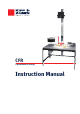
CFR Calibration Facility Instruction Manual
IMPORTANT USER INFORMATION Reading this entire manual is recommended for full understanding of the use of this product. Should you have any comments on this manual we will be pleased to receive them at: Kipp & Zonen B.V. Delftechpark 36, or P.O. Box 507, T F E W : : : : 2628 XH Delft, The Netherlands 2600 AM Delft, The Netherlands +31 (0)15 2755210 +31 (0)15 2620351 info@kippzonen.com www.kippzonen.com Kipp & Zonen reserves the right to make changes to the specifications without prior notice.
Manual version: 0107 2
Declaration of Conformity According to EC guideline 89/336/EEC We Kipp & Zonen B.V. Delftechpark 36 2628 XH Delft Declare under our sole responsibility that the product Type: CFR (version 230 VAC / 50Hz) Name: Calibration Facility for Radiometers To which this declaration relates is in conformity with the following standard Safety standard IEC 1010-1 Following the provisions of the directive. B.A.H. Dieterink President KIPP & ZONEN B.V.
CFR manual Table of contents IMPORTANT USER INFORMATION ............................................................................................................. 1 Declaration of Conformity ............................................................................................................................... 3 Table of contents ............................................................................................................................................ 4 1 Introduction ...........
CFR manual 1 Introduction Dear customer, thank you for purchasing a Kipp & Zonen product. Please read this manual for a full understanding of the use of your Calibration Facility. The CFR Calibration Facility for Radiometers is designed for the calibration of pyranometers by comparison to a reference pyranometer. As such, it offers a simple and traceable solution for quality control of the stability of pyranometers used in a network.The procedure described complies with Annex A.
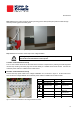
CFR manual 2 Installation and operation 2.1 Delivery Check the contents of the shipment for completeness (see below) and note whether any damage has occurred during transport. If there is damage, a claim should be filed with the carrier immediately. In this case, or if the contents are incomplete, your dealer should be notified in order to facilitate the repair or replacement of the product.
CFR manual 2.2 Installation 2.2.1 Environmental conditions To perform accurate calibrations the calibration facility should preferably be installed in a separate room with temperature controlled and ventilated environment and without spurious light reflections coming from walls and other objects (ideally a dark-room). Kipp & Zonen reference pyranometers are calibrated at approximately + 20 ºC, therefore it is strongly recommended to maintain similar environmental conditions. 2.2.
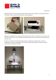
CFR manual Step 3 Remove the mains plug from the lamp housing power cable (if fitted) and pass the cable through the lamp mounting pillar and cable gland. figure 3 Lamp cable passed trough the lamp pillar Step 4 Electrical connection of the lamp to the voltage stabilizer Warning: To prevent electric shock during installation, all electrical devices must be disconnected from the mains power.
CFR manual Step 5 Connect the red and black signal measurement cables to either the back or front input terminals of the voltmeter and to the signal output terminals near the lamp pillar. figure 5 Signal cables between voltmeter and signal output terminals Step 6 The installation will be complete when the mains power cord is connected to an AC power outlet. The lamp of the 230 VAC / 50 Hz Calibration Facility the lamp can be turned on and off using the switch on the power strip.
CFR manual 2.3 Maintenance In general, the manual calibration facility requires little maintenance apart from keeping it clean and checking that mountings, fittings and electrical connections are secure. 2.3.1 Lamp Warning: When cleaning the window or changing the bulb of the calibration lamp for maintenance purposes, the calibration facility should be disconnected from the mains power. The bulb is pressurized and very hot during operation. Allow it to cool down before handling.
CFR manual “fresh” value. If the scale change is more than 1%, critical examination of the radiation centre procedures for old and new references is necessary.
CFR manual There are several procedures for transferring calibration values from a narrow field of view instrument (pyrheliometer) to a wide field of view instrument (pyranometer). For example the direct component of the solar radiation can be eliminated temporarily from the pyranometer by shading the whole outer dome of the instrument with a disk. However, there is no thermal equilibrium with this method and some models of pyranometer show significant zero-offset drift.
CFR manual 3 Calibration operation The indoor calibration procedure, according to ISO 9847 Appendix III, is based on a side-by-side comparison with a reference radiometer under a stable artificial sun. Kipp & Zonen uses a 150 W MetalHalide high-pressure gas discharge lamp with voltage stabilisation. Behind the lamp is a reflector with a diameter of 16.2 cm. The reflector is 115 cm above the radiometers producing a vertical beam. The irradiance at the radiometers is approximately 500 W/m².
CFR manual The possibility of making errors due to inhomogeneous light is still present. Therefore, the positions of the pyranometers are interchanged, to position 2, by rotating the turntable, and the procedure is repeated. The resulting values of this second measurement are called R2 and T2.
CFR manual 3.2 Description of the procedure step-by-step 1. Switch on the lamp and the voltmeter. 2. Place the reference and test pyranometers in the calibration room, outside the lamplight, in order to let their temperatures stabilize. Allow 2 hours for the test pyranometer to stabilize if it has been outdoors. 3. Allow 20 minutes for the lamp to stabilize. 4. Put a test pyranometer and the reference in position marked with reference. Check that the detector surface heights are the same. 5.
CFR manual 3.3 Calibration uncertainty The main purpose of the calibration procedure is to perform a one-to-one comparison of the reference pyranometer and the test pyranometer. In order to achieve this, both pyranometers need to be exposed to exactly the same irradiance, under the same circumstances. There are a number of error sources that could affect the calibration measurement.
CFR manual 3.3.3 Voltmeter offset Theoretically, the voltmeter can cause a zero offset or drift. Short-circuiting the voltmeter input with a resistance equal to the pyranometer’s impedance can check the zero offset. The voltmeter might change sensitivity over the years. Generally it should be regularly recalibrated, as for all test and measurement instruments. Because of the fact that the calibration is a relative measurement, the voltmeter sensitivity is cancelled out of the equations.
CFR manual 3.4 Calibration Form An example of a calibration form is given below. CMP 6 060002 Test pyranometer model: Serial number: CMP 6 060001 10.00 Reference pyranometer model: Serial number: Sensitivity: Calibration performed by: Date: V/Wm -2 (SR) J.
CFR manual 4 Principle components and specifications of the facility The Calibration Facility consists of a number of parts. These are described in the following paragraphs. 4.1 Table The table serves for mounting the lamp, the turntable, the voltage stabilizer (230 VAC version) and the shading mechanism. Additionally, it can serve as a worktable and has clamps for connecting the reference pyranometer signal wires, the test pyranometer signal wires and the voltage meter wires.
CFR manual 4.3 Shading mechanism The shading mechanism serves to obtain the dark (zero-offset) signal of the pyranometers and the measurement chain. The shading mechanism blocks all light illuminated from the lamp. 4.4 Lamp mounting pillar The lamppost serves to position the lamp at a certain height above the pyranometers. In view of the fact that the packaging has to stay within certain limits, the lamppost consists of two parts. The lower part is painted black in order to avoid reflections of the lamp.
CFR manual 4.7 Voltage Stabilization The voltage stabilizer provides a highly stable voltage to the lamp. For calibration it is necessary to have a reliable voltage because variations in lamp output can affect the result of the calibration slightly. In the final calculation there is a check on read-outs and lamp stability. This is shown in chapter 3. For the 230 VAC / 50Hz version the voltage stabilizer is mounted underneath the table.
CFR manual The Kipp & Zonen reference pyranometers are calibrated at the WRC with the sun and sky as the radiation source. As a consequence, in principle, the calibration values obtained for test pyranometers when using the CFR are related to the same outdoor conditions as in Davos. The specific conditions are given in the extended calibration certificate that accompanies the reference pyranometer.
CFR manual 5 Frequently asked questions □ Can I calibrate pyranometers from different manufacturers with the CFR? The CFR is a universal calibration facility using a standardized calibration method that can be applied to any other pyranometer model. Although one should take into account the basic principles of uniformity between the test and reference pyranometer and ensuring equivalent detector heights.
CFR manual Appendix I: Calibration Form for pyranometers Test pyranometer model : ……………………….. Serial number : ……………………….. Reference pyranometer model : ……………………….. Serial number : ……………………….. Sensitivity : ……………………….. V/Wm Calibration performed by : ……………………….. -2 (SR) Signature : ……………………….. Date : ……………………….. Reference pyranometer Test pyranometer R : ……………….. T : ……………….. RE : ……………….. TE : ……………….. R1 = R-RE : ……………….. T1 = T-TE : ……………….. R : ……………….. T : ………………..
CFR manual Appendix II: Pyranometer Classification According to WMO Guide 1996 Characteristics ISO 9060 classification CMP 22 CMP 21 CMP 11 CMP 6 High quality Good quality Moderate quality Secondary Standard Secondary Standard Secondary Standard First Class Secondary Standard First Class Second Class 5s 5s 5s 18 s < 15 s < 30 s < 60 s Response time (95 percent response) Zero offset: 2 (a) Response to 200 W/m net thermal radiation (ventilated) (b) Response 5 K/h change in ambient tem
CFR manual Appendix III: List of World and Regional Radiation Centres World Radiation Centres Davos (Switzerland) St. Petersburg (Russia) (data centre only) Region I (Africa) - Cairo (Egypt) - Khartoum (Sudan) - Kinshasa (Dem. Rep.
CFR manual Appendix IV: Recalibration service Pyranometers, Albedometers, Pyrgeometers, UV-Radiometers & Sunshine Duration Sensors Kipp & Zonen solar radiation measurement instruments comply with the most demanding international standards. In order to maintain the specified performance of these instruments, Kipp & Zonen recommends calibration of their instruments every two years. This can be done at the Kipp & Zonen factory. Here, recalibration to the highest standards can be performed at low cost.
Our customer support remains at your disposal for any maintenance or repair, calibration, supplies and spares. Für Servicearbeiten und Kalibrierung, Verbrauchsmaterial und Ersatzteile steht Ihnen unsere Customer Support Abteilung zur Verfügung. Notre service ‘Support Clientèle’ reste à votre entière disposition pour tout problème de maintenance, réparation ou d’étalonnage ainsi que pour les accessoires et pièces de rechange.