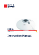
CGR 4 Pyrgeometer Instruction Manual
IMPORTANT USER INFORMATION Reading this entire manual is recommended for full understanding of the use of this product. Should you have any comments on this manual we will be pleased to receive them at: Kipp & Zonen B.V. Delftechpark 36, 2628 XH Delft P.O. Box 507, 2600 AM Delft The Netherlands T: +31 (0) 15 2755 210 F: +31 (0) 15 2620 351 info@kippzonen.com www.kippzonen.com Kipp & Zonen reserves the right to make changes to the specifications without prior notice.
Declaration of Conformity According to EC guideline 89/336/EEC 73/23/EEC We Kipp & Zonen B.V. Delftechpark 36, 2628 XH Delft P.O. Box 507, 2600 AM Delft The Netherlands Declare under our sole responsibility that the products Type: Name: CGR 3 / CGR 4 Pyrgeometer to which this declaration relates are in conformity with the following standards Imissions Emissions EN 50082-1 Group standard EN 50081-1 Group standard EN 55022 Safety standard IEC 1010-1 Following the provisions of the directive. B.A.H.
Table of contents IMPORTANT USER INFORMTION ...................................................................................................... Declaration of Conformity ............................................................................................................... Table of contents ........................................................................................................................... 1. Introduction .....................................................................
1. Introduction Dear customer, thank you for purchasing a Kipp & Zonen instrument. Please read this manual and the separate instruction sheet for a full understanding of the use of your pyrgeometer. A CGR series pyrgeometer is a high quality radiometer designed for measuring long-wave irradiance on a plane surface (radiant flux, W/m2) which results from radiation incident from the hemisphere above the instrument.
2. Installation and operation 2.1. Delivery Check the contents of the shipment for completeness (see below) and note whether any damage has occurred during transport. If there is damage, a claim should be filed with the carrier immediately. In this case, or if the contents are incomplete, your dealer should be notified in order to facilitate the repair or replacement of the instrument. Contents of delivery: 1. Radiometer 2. Sun shield 3. Cable with connector 4. Test reports 5. Instruction sheet 6.
3. Mounting The CGR pyrgeometer is provided with two holes for 5 mm bolts. Two each of stainless steel bolts, washers, nuts and nylon insulation rings are provided in the fixing kit. The pyrgeometer should first be secured lightly with the bolts to a solid and stable mounting stand or platform as shown in Figure 1. After recalibration the nylon insulators must be replaced with new ones to prevent corrosion. The mounting stand temperature can vary over a wider range than the air temperature.
6. Secure pyrgeometer Secure the pyrgeometer tightly with the two stainless steel bolts. Ensure that the pyrgeometer maintains the correct levelled position! 7. Fit cable and sun shield Locate the cable plug correctly in the radiometer socket (it only fits one way) and screw the plug locking ring hand-tight. Finally, clip on the sun shield to prevent excessive heating of the radiometer body. The bubble level is visible through the top of the sun shield for routine checks. 2.2.2.
2.2.4. Installation for shaded measurement of downward long-wave radiation For measuring atmospheric radiation with some pyrgeometers, such as the CGR 3, it is desirable to shield the instrument from the direct short-wave solar radiation which may heat up the pyrgeometer dome or window and cause significant thermal offsets. The direct solar radiation is intercepted by a small disk or sphere. The shadow of the disk must cover the pyrgeometer dome completely.
However, if the upward and downward radiation components are to be measured separately it is necessary to record the individual housing temperatures to calculate the radiation values. Using the combination of a net pyrgeometer (two CGR 3 or CGR 4 instruments) and a CMA 6 or CMA 11 albedometer the net total radiation (energy balance) can be calculated with high accuracy from thefour component values.
2.2.4. Installation for shaded measurement of downward long-wave radiation For amplification of the pyrgeometer signal Kipp & Zonen offers the AMPBOX signal amplifier. This amplifier will convert the micro-Volt output from the pyrgeometer into a standard 4 – 20 mA signal. The use of the AMPBOX amplifier is recommended for applications with long cables (> 100m), electrically noisy environments or data loggers with a current-loop input.
2.4.1. Overcast sky Typical for a cloudy overcast sky is that radiation emitted by the earth is absorbed 100% by the clouds. Therefore, the overcast sky will re-emit the radiation (Ld) 100%. In theory, the net radiation (Uemf / S) will be zero, so the pyrgeometer detector output voltage (Uemf) will be zero. In practice, the detector output shows a small negative voltage (a few W/m²), due to a small heat exchange between the relatively warm pyrgeometer and the colder sky.
2.4.3. Measurements during a sunny day The CGR 4 differs from all other pyrgeometers in that it allows accurate daytime measurements on sunny days without the need for a shading device. Due to the unique construction of the CGR 4, solar radiation of up to 1000 W/m² induces window heating of less than 4 W/m² in the overall calculated downward radiation. Formula 1 can be applied without any problems with the following exception; one must take note of the amount of Infrared radiation in the solar spectrum.
For the CGR 4 the effect of each parameter on the sensitivity can be shown separately. The non-linearity error, the sensitivity variation with irradiance, is the same for any CGR 4 and is shown in Figure 8. Figure 8: Non-linear sensitivity variation with irradiance of a CGR 4 pyrgeometer The temperature dependence of the sensitivity is a function of the individual CGR 4. For a given CGR 4 the response lies in the region between the curved lines in Figure 9.
2.6. Maintenance Once installed the pyrgeometer needs little maintenance. The dome/window must be cleaned and inspected regularly, ideally every morning. On clear windless nights the dome/window temperature of horizontally placed pyrgeometers will decrease, even to the dew point temperature of the air, due to infrared radiation exchange with the cold sky. (The effective sky temperature can be 30°C lower than the ground temperature).
3. Principle components of pyrgeometers The detector of the Kipp & Zonen CGR series pyrgeometer is based on a passive thermal sensing element called a thermopile. Although the detector construction differs from model to model, the fundamental working principle is applicable to all CGR series radiometers. The thermopile responds to the total power absorbed by the black surface coating, which is a nonspectrally selective paint, and warm up.
The solar blind filter is opaque to radiation below 4.5 µm, known as the cut-on wavelength. Currently most pyrgeometers have their cut-on at a lower wavelength. Problems may occur in the case of clear sunny days with low humidity. In the solar spectrum between 2.5 and 4.5 µm there can still be an amount of infrared solar radiation up to 10 W/m², which should not be included in the measurement. This unwanted fraction is blocked in the CGR 4 by the filter coating.
3.4. Housing The radiometer housing accommodates all fundamental pygeometer parts. The anodized Aluminium parts are light weight and give a high mechanical and thermal stability to the instrument. Due to its fine mechanical construction all pyrgeometers are virtually sealed and comply to the international standard IP 67. Each pyrgeometer model can be leveled by using the bubble level and two leveling feet.
4. Pyrgeometer physical properties 4.1. Spectral range The spectral properties of the pyrgeometer are mainly determined by the filter characteristics of the silicon window and the coatings. The application is primarily to measure long-wave downward atmospheric radiation. The spectral range is from 4.5 to 42 µm, where most of this radiation is present.
4.2. Sensitivity The radiometer thermopile sensitivity is mainly determined by the physical properties of the detector itself. The thermoelectric power, thermal conductivity of the junctions and the overall dimensions of the sensing element are related to its sensitivity. 4.3. Impedance The radiometer impedance is defined as the total electrical impedance at the radiometer output connector fitted to the housing.
4.8. Window heating offset Currently the major source of error concerning common pyrgeometer measurements is caused by the so-called ‘window heating offset’. When a pyrgeometer is exposed to the sun, heating of the silicon dome/window occurs due to absorption of solar radiation by the material. As a consequence the dome/window of most types of pyrgeometer will heat up proportionally to the solar irradiance.
4.10. Operating temperature The operating temperature range of the radiometer is determined by the physical properties of the individual parts. Within the specified temperature range Kipp & Zonen radiometers can be operated safely. Outside this temperature range special precautions should be taken to prevent any physical damage or performance loss of the radiometer. Please contact your distributor for further information regarding operation in unusually harsh temperature conditions. 4.11.
4.16. Environmental The CGR series are intended for outdoor use under all expected weather conditions. The radiometers comply with IP 67 and their solid mechanical construction is suitable to be used under all environmental conditions within the specified ranges. 4.17. Uncertainty The measurement uncertainty can be described as the maximum expected hourly or daily uncertainty with respect to the ‘absolute truth’.
5. Calibration 5.1. Calibration principle An ideal radiometer gives voltage output that is proportional to the absolute irradiance level. This relationship can be expressed as a constant ratio called ‘sensitivity’ (Sensitivity). The sensitivity figure of a particular pyrgeometer is unique. In the case of the CGR 4 it is determined outdoors by comparison against a reference CGR 4 pyrgeometer. The reference pyrgeometer is calibrated outdoors regularly at the World Radiation Centre (WRC) at Davos, Switzerland.
6. CGR models The CGR series comprises 2 models, CGR 3 and CGR 4. The mechanical construction of the CGR 3 differs from the CGR 4 in that it has a flat silicon window, smaller housing dimensions and no drying cartridge (the housing is completely sealed). Features and specifications of the CGR 4 pyrgeometers are given in this chapter. The CGR series is designed for measuring the downward radiation (W/m²) on a plane surface from the atmosphere above.
6.2.
6.3.
7. Frequently asked questions The most frequently asked questions are listed below. For an update refer to the Kipp & Zonen website at www.kippzonen.com - What are typical values for downward atmospheric long wave radiation? - The values calculated with the formula given in chapter 2 show a very strange value. What could be the reason? - Check whether the (instrument) temperature (Tb) is given in Kelvin.
8. Trouble shooting The following contains a procedure for checking the instrument in case it appears that it does not function as it should. Trouble shooting: Output signal fails or shows improbable results; - Check the wires are properly connected to the readout equipment. Check the dome, it should be clear and clean. If water is deposited on the inside, please change the desiccant. If too much water is deposited internally the drying cartridge should be removed and the instrument warmed to dry it.
Appendix I Radiometric terminology Term Explanation Azimuth angle Angle in horizontal direction (0-360°) Angle of incidence Incident angle from zenith (vertical) Cosine response Detector response according to the cosine law Global solar irradiance Total irradiance falling on a horizontal surface (Diffuse+Direct • cos α) Irradiance Radiant flux density (W/m²) Long-wave radiation Radiation with wavelengths > 4 µm and < 100 µm Long-wave downward radiation Radiation emitted by the sky Net radiation
Appendix II 10kΩ thermistor specifications YSI Thermistor 44031 - Resistance versus Temperature in °C Thermistor (10 kΩ @ 25ºC) -1 T = (α + [β • (ln(R))+γ •(ln(R))3]) -273.15 α : 1.0295 • 10 -3 β : 2.391 • 10 -4 γ : 1.
Appendix III Pt-100 specifications Pt-100 - Resistance versus Temperature in ºC and ºF T [ºC ] = Temperature R [Ω ] = Resistance Page 32 CGR 4 Manual Pt-100 (100 Ω @ 0ºC) - α + α2- 4 • β • T= -R +1 100 2•β α : 3.9083 • 10 -3 β : -5.
Appendix IV List of World and Regional Radiation Centres World Radiation Centre The World Radiation Centre capable of pyrgeometer calibration is located at: Physikalisch-Meterologisches Observatorium Dorfstrasse 33 CH-7260 Davos Dorf Switzerland Website: www.pmodwrc.
Appendix V Recalibration service Pyranometers, Albedometers, Pyrgeometers, UV-Radiometers & Sunshine Duration Sensors Kipp & Zonen solar radiation measurement instruments comply with the most demanding international standards. In order to maintain the specified performance of these instruments, Kipp & Zonen recommends calibration of their instruments every two years. This can be done at the Kipp & Zonen factory. Here, recalibration to the highest standards can be performed at low cost.
Our customer support remains at your disposal for any maintenance or repair, calibration, supplies and spares. Für Servicearbeiten und Kalibrierung, Verbrauchsmaterial und Ersatzteile steht Ihnen unsere Customer Support Abteilung zur Verfügung. Notre service 'Support Clientèle' reste à votre entière disposition pour tout problème de maintenance, réparation ou d'étalonnage ainsi que pour les accessoires et pièces de rechange.