CM 121 Shadow Ring Instruction Manual
IMPORTANT USER INFORMATION IMPORTANT USER INFORMATION Reading this entire manual is recommended for full understanding of the use of this product. Should you have any comments on this manual we will be pleased to receive them at: Kipp & Zonen B.V. Delftechpark 36 2628 XH Delft Holland P.O. Box 507 2600 AM Delft Holland Phone +31 (0)15 2755210 Fax +31 (0)15 2620351 Email info@kippzonen.com Web www.kippzonen.com Kipp & Zonen reserve the right to make changes to the specifications without prior notice.
IMPORTANT USER INFORMATION 2 Instruction manual CM 121
TABLE OF CONTENT TABLE OF CONTENT IMPORTANT USER INFORMATION.............................................................................................1 TABLE OF CONTENT ...................................................................................................................3 1. INTRODUCTION ........................................................................................................................5 2. UNPACKING AND ASSEMBLING.........................................................
TABLE OF CONTENT 4 Instruction manual CM 121
1. INTRODUCTION 1. INTRODUCTION The combination of a CM 121 shadow ring and a pyranometer offers a simple solution for the measurement of the diffuse solar radiation.
1.
2. UNPACKING AND ASSEMBLING 2. UNPACKING AND ASSEMBLING 2.
2. UNPACKING AND ASSEMBLING figure 1.
2. UNPACKING AND ASSEMBLING 2.2 CM 121C Packed in the CM 121C transport box are the same items as with the CM 121B plus: z z z z CV 2 adapter Two spacers Two cap screws M6 x 10 Two cap screws M5 x 16 After removing the ties with which the items are connected to the transport box, the shadow ring can easily be assembled. z z z z Place the pillar in between the base and the crossbar, using the thread Place the CV 2 adapter (see figure 1.
2. UNPACKING AND ASSEMBLING CV2 R em ove a d ju s ta b le fe e t (2 x ) S p a c e r (2 x ) C V 2 a d a p te r M 6 x 1 0 c a p s c re w (2 x ) C V 2 + C V 2 a d a p te r M 5 x 1 6 c a p s c r e w (2 x ) CM 121B In s ta lla tio n d ra w in g C V 2 + C M 1 2 1 B D o c u m e n t n u m b e r : 5 3 5 - 0 3 4 6 7 0 0 -4 0 D a te : 2 0 0 2 -0 9 - 1 1 figure 1.
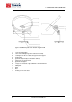
3. PRINCIPLES & SPECIFICATIONS 3. PRINCIPLES & SPECIFICATIONS 3.1 Theory The objective of the shadow ring is to intercept the direct radiation coming to the pyranometer from the sun during the whole day without readjustment. Therefore the shadow ring must satisfy the following requirements. See also the schematic representation (fig. 2). z z z Once installed, the axis of the shadow ring must be always parallel to the polar-axis.
3. PRINCIPLES & SPECIFICATIONS 3.2 Construction The crossbar is one of the main parts of CM 121B. By rotating the crossbar the angle between shadow ring axis and horizontal earth surface can be set for the particular location. This is an operation that needs to be performed only once for installation at a certain location. The pyranometer support is fixed to the crossbar, so the sensor stays in the center of the ring no matter the tilt angle of the ring.
3.
4. MOUNTING AND ALIGNMENT 4. MOUNTING AND ALIGNMENT 4.1 Introduction The CM 121B can be mounted on any surface that is within one degree horizontal. It can also be mounted on a tilted plane, if that plane faces south or north within 1/4 degree. As explained in the previous chapter, the CM 121B has to be aligned north-south and the sliding bars must be tilted and brought parallel to the polar axis. These two steps are described below.
4. MOUNTING AND ALIGNMENT z z Check the next sunrise and sunset if the dome is still shaded. If not, note if the change between sunrise and sunset is symmetrical, and make corrections. For permanent installation it is recommended to secure the position of the shadow ring by connecting its base to a solid underground. Figure 5 can be used for finding the proper position for clamps or bolts. figure 3.
4. MOUNTING AND ALIGNMENT figure 4. set up to align the sight in the sector with the sun at 12.00 True Solar Time figure 5.
4. MOUNTING AND ALIGNMENT 4.3 Tilting of the sliding bars (one time installation) The purpose of this step is to bring the sliding bars parallel to the polar axis. This can be done by rotating the crossbar after having unscrewed the securing bolt and relocking it in the required tilted position. When correctly aligned the angle between sliding bars and the horizontal should equal the geographical latitude. See figure 2.
4. MOUNTING AND ALIGNMENT 4.4 Setting of the shadow ring sliding bars (regular servicing procedure) The correct shadow ring position is a function of the declination of the sun and it varies across the year. The only thing that needs to be done to readjust the position of the ring is to set the sliding bars. A readjustment is necessary only after a few days. A regular schedule would require redjustment every two days. However, in most seasons a longer time interval between adjustments is possible.
5. MEASUREMENT OF THE DIFFUSE SKY RADIATION 5. MEASUREMENT OF THE DIFFUSE SKY RADIATION 5.1. The shadow ring correction A pyranometer equipped with a shadow ring is measuring the downward diffuse solar radiation as received by a horizontal surface from a solid angle of 2π with the exception of the solid angle subtended by the shadow ring. To obtain an estimation of the radiation that would be received from the whole hemisphere if the ring were not present, a correction must be introduced.
5.
5. MEASUREMENT OF THE DIFFUSE SKY RADIATION 5.3 Diffuse sky radiation on a tilted plane The correction factors are only valid for a pyranometer in the horizontal position. However, for a pyranometer tilted T degrees to the south and on latitude B, the configuration of ring and pyranometer is the same as for a horizontal pyranometer at latitude (B - T) degrees. You can derive a list of correction factors for a tilted pyranometer from table 1 in 5.
5.
6. APPENDIX 6. APPENDIX 6.1 Theoretical derivation of the correction factor, for uniform sky radiation The relation between the correction factor C and the intercepted part S of the downward component of the sky radiation is C = 1 / (1 -S) (6.1) S can be expressed in the view angle V of the ring, the sun's declination D and the latitude B of the observation site. Let U0 be the angle between the sun at sunrise (or at sunset) and the sun at true noon in the plane of the ring.
6. APPENDIX The influence of the sliding bar parts rising above the horizon is neglected. To compare: the formula for a flat shadow band is S = 2W . cos3 . D . (U0 . sinB . sinD + sinU0 . cosB . cosD) / π. R (6.9) W is the ring width and R is the ring radius. A comparison is shown in figure 6. figure 6 24 the view angle of the U-profile shadow ring as a function of the solar declination, in comparison to a conventional flat shadow band.
6.
Our customer support remains at your disposal for any maintenance or repair, calibration, supplies and spares. Für Servicearbeiten und Kalibrierung, Verbrauchsmaterial und Ersatzteile steht Ihnen unsere Customer Support Abteilung zur Verfügung. Notre service 'Support Clientèle' reste à votre entière disposition pour tout problème de maintenance, réparation ou d'étalonnage ainsi que pour les accessoires et pièces de rechange.