
Owner's manual

.
Please follow the instructions in this section carefully for the mechanical and electrical installation of the LAS MkII scintillometer.
Do not turn on power to the transmitter or receiver until instructed to do so.
Ensure that fixings and mountings are securely tightened when instructed to do so.
2.1 Included with the product
Check the contents of the shipment for completeness (see below) and note whether any damage has occurred during transport. If
there is damage, a claim should be filed with the carrier immediately. In the case of damage and/or the contents are incomplete,
contact your local Kipp & Zonen representative or e-mail the Kipp & Zonen customer and product support department at:
support@kippzonen.com
Note The LAS MkII is rugged, but it contains sensitive optical and electronic parts. Please keep the original packaging
to safely transport the scintillometer to measurement sites or for other shipments.
The following items are included with the LAS MkII scintillometer:
LAS MkII transmitter with pan and tilt adjuster and baseplate
LAS MkII receiver with pan and tilt adjuster and baseplate
2 × alignment telescope with detachable mounting, adjusted for each transmitter and receiver
2 × sun shield with two fixing screws
2 × 100 mm diameter aperture restrictor with fixing kit, for transmitter and receiver
2 × 10 m cable with 4-pin plug for transmitter signal output and receiver analogue connections
1 x 10 m cable with 8-pin plug for receiver digital communication connections
2 x 10 m cable with 4-pin connector for 12 VDC power input
2 x 3 mm hexagonal Allen keys, for fitting the sun shields
2 x 4 mm hexagonal Allen keys, for fitting the telescopes
1 x CD-ROM containing EVATION software and a pdf file of this LAS MkII instruction manual
8 x spare desiccant packs
23
Instruction Manual - LAS MkII Scintillometer
.
2.5.3 Receiver Analogue signal connector
The receiver is provided with a 4-pin plug for analogue signal outputs, fitted to a 10 m long yellow cable that is terminated in
tinned wires.
Receiver analogue signal connector and cable
2.5.4 Receiver digital interface connector
The receiver is provided with an 8-pin waterproof plug for the digital communication interface, fitted to a 10 m long yellow cable
that is terminated in tinned wires.
Two communication modes can be selected, RS-232 or 4-wire RS-422 (default). The desired mode can be selected using the LAS MkII
configuration menu or by the control software.
Receiver digital interface connector and cable
For permanent connection to a computer always use optically or galvanicly isolated adapters or converters at the
computer serial port to protect against damage caused by lighting.
.
2.1.1 The transmitter
The transmitter housing contains a very efficient, eye-safe LED operating at 850 nm wavelength in the near-infrared region. The
LED mounting is axially adjustable to position it at the focus of a Fresnel collimating lens. The near-parallel beam is output
through a glass window with an aperture diameter of 150 mm. There is a self-regulating heater for the window that can disperse
rain, dew, frost and snow. Electronics pulse the LED at 6.5 - 7 kHz and the drive signals can be monitored on the signal output
connector.
There is a baseplate with rugged and easy to use pan and tilt adjustment. A mounting rail on the top of the housing is used to
fit the alignment telescope or the white heat shield. There are two drying cartridges containing desiccant to keep the transmitter
dry internally.
The transmitter is powered by 12 Volts DC.
.
2.5.5 Receiver meteorological sensor kit connector
The 8-pin connector marked ‘Sensors’ must only be used with the accessory meteorological sensor kit. The 12 VDC
output must not be used to supply other equipment.
Receiver meteorological sensor kit connector
The accessory meteorological sensor kit is supplied pre-wired with a 10 meter long yellow cable and waterproof connector and
will be automatically powered and recognised when plugged into the LAS MkII receiver.
Do not connect a computer to the sensor connector using the digital interface plug and cable. The 12 V power
output for the sensors may damage the computer serial port.
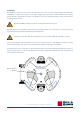
2.6 Aperture restrictors for short range applications
In case the LAS MkII is required to operate over short distances the aperture diameter of the transmitter and receiver can be
reduced to 100 mm using the supplied restrictors. The LAS MkII can then be used over path lengths from 100 m to 1 km.
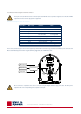
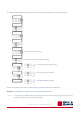
To fit the restrictors proceed as follows and shown in the diagram below:
1. Remove 3 of the 6 retaining screws of the transmitter and receiver windows
2. Replace the screws by the nylon spacers
3. Secure the restrictors using the M4 x 25 mm cap-head screws and nylon washers
When using the restrictors, remember to set the aperture values in the LAS MkII configuration menu to 100 mm.
As the beam diameter becomes smaller so does the beam divergence. This means that the alignment of the 100 mm
LAS MkII may be more critical than for the full-beam 150 mm LAS MkII. It is recommended to use very stable
mounting constructions.
2.7 Using the display and key-pad
The waterproof display and menu navigation keys located on the rear panel of the LAS MkII receiver allow for complete instru-
ment configuration and control without the need for additional computers, cables and software. This section describes the basic
procedure for navigating through the menus, changing and confirming settings.
Note The complete menu structure of the LAS MkII scintillometer can be found in Appendix C.
Navigating through the LAS MkII menu structure is very straight-forward using the keys.
The keys are used to scroll through the (sub-) menus or to select or enter a value:
Scroll mode:
Up key Select next menu item
Down key Select previous menu item
Left key Go one menu level back
Right key Select displayed menu item
Edit mode
Up key Increment digit
Down key Decrement digit
Left key Select previous digit
Right key Select next digit
Confirm (edit mode)
Display shows Confirm Entry - Yes
Up or down key Cycles through options; Yes, No, Quit
Right key Completes selected action:
Yes - confirm changes and go back to menu
No - cancel and go back to edit mode
Quit - exit edit mode without changes
.
For example to change the path length setting from 110.0 m to 1250.0 m the following actions need to be performed:
In order to keep this manual as concise as possible, this process will be shortened in the following way:
Main Menu → 2. Configuration → 1. Installation → 2. Path length → 1250.0 m → Confirm
Note To reduce power consumption and increase life-time, the receiver display is turned off if no keys are pressed for
4 minutes. Pressing any key turns the display on again.
2.8 Configuration for measurement
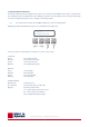
The table below shows the sub-menus contained within Menu 2, Configuration. These sub-menus require setting up before, or
during, installation. To configure the LAS MKII receiver before installation refer to the ‘power up receiver’ section 2.9.4.
Note The complete menu structure of the LAS MkII scintillometer can be found in Appendix C.
Note The Sensor sub-menu default values are used when the meteorological sensor kit is not connected. These values
can be changed by the user, within the ranges shown.
Note If a BaudRate is entered different to those listed, the receiver will select the nearest valid value.
Valid interface types are 232 and 422, if another number is entered the port will switch off.
.
2.8.1 Setting parameters to measure C
n
2
C
n
2
is measured using the following general algorithm:
Where; D is the aperture diameter of the LAS MkII, L is the distance between the transmitter and the receiver (the path length)
and σ
lnI
2
the measured variance of the natural logarithm of intensity fluctuations.
The parameters for aperture and path length must be set in the receiver.
Note Set the Aperture to the value stated on the Test and Final Inspection Certificate supplied with the instrument. The
typical setting is 149 mm.
2.8.2 Setting parameters to measure sensible heat flux
From C
n
2
data, together with wind speed, temperature, and an estimate of the topology and the displacement height; the surface
sensible heat flux (H) can be determined from by solving equations iteratively. See Appendix C for further information.
In addition to the parameters for measurement of C
n
2
the following additional parameters are required to measure surface sensi-
ble heat flux (H):
• Installation height
• Zero Displacement Height
• Bowen Ratio
• Temperature
• Pressure from meteorological sensor kit when connected
• Wind Speed
• Roughness Length
The surface sensible heat flux (H) can be calculated by a computer using the supplied EVATION software package, the data from
the LAS MkII and meteorological sensor kit and by inputting other parameters, such as the roughness length.
However, for most day-time (unstable) conditions and when the LAS MkII is installed relatively high above the surface (z
LAS MkII
> 20 m) the contribution of the friction velocity is relatively small. For these conditions the free convection method can be
applied.
Note that the free convection sensible heat flux (H
free
) calculated by this method is not as accurate as the standard method for H
because it does not allow for surface topography (roughness length, etc.).
See Appendix C for further information.
When the meteorological sensor kit is connected the LAS MkII can internally calculate and log the free convection sensible heat
flux (H
free
).
2.8.3 External sensors
When the meteorological sensor kit is connected the correct factory sensitivities and ranges are automatically selected.
When the kit is not connected, fixed values typical of the measurement location can be entered in sub-menu 3 of the configuration menu.
.
2.8.4 Data Logger
Configure the following data logger settings; date, time, sleep time, wakeup time, log-interval and send interval.
The wakeup time defines the start of the operational mode. When the operational mode is active the LAS is measuring and
logging data; the receiver heater is turned on when the temperature of the receiver is below the ‘operating temperature’ in the
heater menu.
The sleep time defines the start of the low power ‘sleep’ mode, during which there is no measurement and the receiver heater is
turned on only when the temperature of the receiver is below the ‘standby temperature’ in the heater menu.
The log interval defines the interval over which measurements will be averaged and then stored in the internal flash data memory.
The send interval defines the interval at which the current data values will be sent automatically to a computer.
2.8.5 Interface
Configure the following interface settings; baud rate, parity, data bits and interface type.
.
2.1.2 The receiver
The beam from the transmitter enters the receiver through a glass window with an aperture diameter of 150 mm. There is a
self-regulating heater for the window that can disperse rain, dew, frost and snow. A Fresnel lens focusses the 6.5 - 7 kHz pulsed
radiation onto a very sensitive large-area photodiode detector with a thin-film optical filter that only transmits radiation in a
waveband around 850 nm, blocking ambient light from reaching the detector. The detector and filter assembly are axially
adjustable to position the detector at the focus of the lens.
Analogue electronics are tuned to the 6.5 - 7 kHz carrier wave and to the scintillation frequency band of 0.2 Hz to 400 Hz. These
signals are rectified and are available at the analogue signal connector. All the remaining electronics are digital. The system can
be locally configured at the receiver with a display and menu navigation keys and has internal signal and data processing and
storage. It can calculate and log Cn2 measurements and, with the accessory meteorological sensor kit connected, the sensible
heat flux (H) can be calculated and stored. External communication is via the digital interface connection.
There is a baseplate with rugged and easy to use pan and tilt adjustment. A mounting rail on the top of the housing is used to
fit the alignment telescope or the white heat shield. There are two drying cartridges containing desiccant to keep the receiver
dry internally.
The receiver is powered by 12 Volts DC.
.
2.1.3 Alignment telescopes
Each transmitter and receiver has a telescope, individually adjusted to align with its optical axis, and each telescope is labelled
accordingly. These telescopes attach by clamps to mounting rails on the tops of the transmitter and receiver housings and enable
alignment of the transmitter and receiver at long path lengths. They are not completely weatherproof and should be removed after
alignment and replaced by the sun shields. A 4 mm hexagonal Allen key is supplied for the mounts of each telescope.
2.1.4 Sun shields
After alignment of the transmitter and receiver the telescopes should be removed and replaced by the sun shields. These are each
attached by two screws to mounting rails on the tops of the transmitter and receiver housings. A 3 mm hexagonal Allen key is
supplied for the fixing screws of each sun shield.
.
2.1.5 Aperture restrictors
The full beam aperture of 150 mm enables operation over path lengths from 250m to 4.5 km, depending upon the atmospheric
conditions. For shorter path lengths, from 100m to 1 km, restrictors with apertures of 100 mm are fitted in front of the windows of
the transmitter and receiver.
2.1.6 Power cables
Two 10 m long cables with 4-pin waterproof plugs are provided for the transmitter and receiver 12 Volt DC power inputs.
2.1.7 Signal cables with 4-pin plugs
Two 10 m long cables with 4-pin waterproof connectors are provided. One for the transmitter signal outputs, the other for the
receiver analogue signal connection.
2.1.8 Signal cable with 8-pin plug
One 10 m long cable with an 8-pin waterproof plug is provided for the receiver digital interface connection.
.
2.1.9 Allen keys
Two 3 mm hexagonal Allen keys are supplied for fitting the transmitter and receiver telescopes and two 4 mm hexagonal Allen keys
for fitting the sun shields.
2.1.10 CD-ROM
The supplied CD-ROM contains the EVATION software package and this manual as a pdf file.
2.1.11 Desiccant packs
Eight spare packs of self-indicating silica gel desiccant are supplied for the drying cartridges of the transmitter and receiver.
2.2 tools required
In addition to the items supplied with the LAS MkII scintillometer, the following equipment is required for performing the installation:
• At least two people
• Stable mounting bases for the transmitter and receiver or tripods
• Printed copy of the manual, from the supplied CD-ROM
• Tape measure for determining the installation height
• 2 x radios or mobile ‘phones for communication between transmitter and receiver operators
• 2 x sets of mounting bolts and suitable wrenches
• 2 x sources of 12 Volts DC power
2.3 Location and support base
When choosing the location for scintillometer measurements care has to be taken that certain requirements are met.
2.3.1 Path orientation and avoiding direct sunlight
Avoid locating the transmitter and receiver where direct sunlight may be in their views. The Fresnel lenses will focus the light onto
the transmitting LED and the receiving optical filter and photodiode and there is a risk of damage due to overheating.
It is recommended to select a path that is approximately parallel to the Earth’s surface (i.e. horizontal) and has a north-south
orientation to avoid any problems caused at low sun angles. If this is not possible, pick an orientation where some obstruction in
the background (buildings, trees) blocks the direct sun.
Direct sunlight close to the optical axes of the transmitter and receiver may permanently damage optical parts.
In order to maximise the footprint of the measurement, it is recommended to select a path between the transmitter and receiver
which is perpendicular to the predominant wind direction.
Ensure that the optical path between the transmitter and receiver is free of any obstructions.
2.3.2 Minimum installation height to prevent saturation
When the scintillation intensity rises above a certain limit the theory, on which the scintillation measurement method is based,
is no longer valid. When this occurs, the relationship between the measured amount of scintillations (σ
lnI
2
) and the structure
parameter of the refractive index of air (C
n
2
) fails. This phenomenon is known as saturation.
In order to prevent saturation, C
n
2
must stay below a certain saturation criterion (S
max
), i.e. the scintillometer can measure well
only under weakly scintillating conditions. The dependence of C
n
2
on the optical wavelength (λ), the aperture diameter (D), the
measurement height (z
LAS
) and the path length (L) can be written as follows:
C
n
2
(λ, D, z
LAS
, L) S
max
The path length and the measurement height are the only variables that can be adjusted in order to keep C
n
2
below the saturation
criterion. A scintillometer installed at a height close the Earth’s surface; will see more scintillations than a scintillometer
installed high above the surface. As the path length increases more scintillation will be observed.
.
This means that over long distances (several kilometres) the scintillometer must be placed high above the surface in order to
prevent saturation. Over shorter distances (several hundred meters) the scintillometer can be installed closer to the surface.
Over dry areas the surface sensible heat flux is large, resulting in higher C
n
2
values than over wet surfaces where the sensible
heat flux is small.
The graphs below show the minimum height of the LAS MkII for different surface conditions as a function of the path length. The
area above the curves in the figure is the so-called non-saturation zone. Below the curves saturation will occur. Based on the
user’s preferred path length, and the surface conditions of the area of interest, the user must install the LAS MkII scintillometer
at a height that lies in the non-saturation zone.
Full 150 mm aperture
Restricted 100 mm aperture
.
For example, a LAS MkII installed over a relatively wet area (h ~ 100 W/m²) and a path length of 3 km must be installed at a
height of at least 12 m.
Ensure that the LAS MkII is operating in the ‘non-saturation’ zone.
.
2.3.3 Effective beam height
Determine the effective height of beam of the LAS MkII (z
LAS
) along the path precisely. The surface sensible heat flux (H) derived
from the structure parameter data is very sensitive to the height (see Appendix A). When the area is relatively flat and the beam
is parallel to the surface the effective height is easy to determine (z
transmitter
= z
receiver
= z
LAS
).
The path-weighting function is symmetrical and bell-shaped having a centre maximum and tapering to zero at the transmitter
and receiver end. This means that the LAS MkII is most sensitive in the middle of its path. For situations where the area is not
flat, or for slanted paths, it is recommend to measure the height of the beam at several points along the path.
The figure below shows how the weighting function must be used in order to estimate the precise height of the beam above the
surface for non-flat areas. The effective height calculator in the EVATION software package can be used to find the effective
height, as described in Appendix E. For more information see Hartogensis et al, 2003
1
.
The graphs above illustrate a LAS MkII path (beam) over a non-flat area. Based on the elevation map (surface) and the LAS
path-weighting function, an effective beam height of 46 m was calculated.
1
Hartogensis, O.K., Watts, C.J., Rodriguez, J-C. and De Bruin, H.A.R.: 2003, ‘Derivation of an Effective Height for Scintillometers: La Poza Experiment in Northwest Mexico’, J. Hydro-Meteorol. 4, 915-928.
.
2.3.4 Operation in the constant flux layer
In order to derive the surface fluxes of sensible heat from the scintillometer measurements (C
n
2
) we use the Monin-Obukhov Similarity
Theory (MOST) (see Appendix A). MOST is widely used in meteorology and is usually applied to the Surface Layer (SL) and hence is
sometimes called the Surface Layer Similarity. The SL is roughly the lowest 10% of the Planetary Boundary Layer (PBL).
.
The PBL is directly influenced by the earth’s surface and its depth varies between roughly 100 m and 2 km. In general the PBL
increases during the day, when the Earth’s surface is heated by the sun, and decreases again during the night. Within the SL the
variation of fluxes (such as the sensible heat flux H and latent heat flux L
v
E) is negligible with respect to the magnitude of their
value at the surface.
Therefore, fluxes measured at a certain elevation in the SL can be considered as being representative of the exchange processes
occurring between the Earth’s surface and the atmosphere above. The SL can be further divided into the Roughness Sub-layer
(RS), influenced by the structure of the roughness elements (e.g. plants, trees, buildings etc.), and the Constant Flux Layer
where fluxes are assumed to be horizontally and vertically constant (due to turbulent mixing). This means that measurement
techniques that apply MOST for estimating surface fluxes can be applied only in the Constant Flux Layer.
Therefore the LAS MkII must be installed at a height such that it is located above the Roughness Sub-layer and is measuring
within the Constant Flux Layer.
The depth of the SL typically varies between 20 m and 100 m. The upper level strongly depends on the diurnal cycle of surface
heating and cooling and the presence of clouds. Like the PBL, the SL increases during the day as the surface is heated by the sun
and is maximum at sunset (~100 m), before it decreases again due to cooling of the surface at night (~20 m).
The height of the Roughness Sub-layer, and thus the lower level of the Constant Flux Layer, depends strongly upon the size, form
and distribution of the roughness elements. Usually, over tall vegetation, the height of the Roughness Sub-layer is taken to be
equal to three times the obstacle height (or roughness elements h).
In case the estimated height of the Roughness Sub-layer is below the minimum height to avoid saturation, use a height that
ensures the LAS MkII is in the non-saturation zone.
Ensure that the LAS MkII is measuring in the Constant Flux Layer and in the non-saturation zone.
Note More detailed information about the theory of the scintillation technique can be found in Appendix A.
Note A list of symbols and abbreviations can be found in Appendix B.
2.4 Mounting
The LAS MkII can only function properly when the transmitter and receiver are precisely optically aligned. By mounting the
scintillometer on a stable support, signal loss and regular re-alignment procedures will be avoided. Vibrations in the mounting
structure must be prevented, which can lead to overestimated C
n
2
values. This particularly applies to masts or towers that can
bend and vibrate in the wind.
Mount the LAS MkII transmitter and receiver on stable and vibration-free supports.
Adjustable tripods are only suitable for short-term measurements. Where they are not on hard surfaces, a board should be used
to prevent the tripod legs sinking in and affecting the beam alignment.
If tripods are used, ensure that they cannot easily fall over and possibly damage the transmitter or receiver.
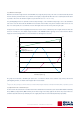
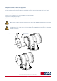
The pan and tilt adjusters of the transmitter and receiver have a baseplate. This has a central M16 thread to fit the mounting
bolts of industrial tripods, such as the accessory adjustable heavy-duty tripod package for the LAS MkII.
The baseplate has 4 slots for 10 mm bolts, on 184.2 mm diameter, which can be used for fixing the transmitter and receiver to a
customer-supplied support or to the accessory Kipp & Zonen tripod floor stand and/or height extension tube. The bottom view
of the baseplate is shown below.
2.5 Electrical and data connections
There are two waterproof connectors located on the rear panel of the transmitter and four on the rear panel of the receiver.
2.5.1 Power connector
The transmitter and receiver are each provided with a 4-pin waterproof plug fitted to a 10 m long cable that is terminated in
tinned wires, for 12 Volts DC (nominal) power to the instrument and heater.
Transmitter and receiver power connector and cable
The LAS MKII transmitter and receiver must be grounded through the shield of the power connector (also connected
to pin 4) for protection against lightning and electrical interference.
The LAS MKII transmitter and receiver power inputs should be protected by fuses.
Instrument power +, 1 A normal or slow-blow type. Heater power +, 4 A slow-blow type.
2.5.2 Transmitter signal output connector
The transmitter is provided with a 4-pin plug for signal outputs, fitted to a 10 m long yellow cable that is terminated in tinned wires.
Transmitter signal connector and cable
M16 threaded hole
Mounting slots for
4 x 10 mm bolts on
184.2 mm diameter