
Owner's manual


34
Instruction Manual - LAS MkII Scintillometer
.
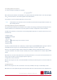
2.5.3 Receiver Analogue signal connector
The receiver is provided with a 4-pin plug for analogue signal outputs, fitted to a 10 m long yellow cable that is terminated in
tinned wires.
Receiver analogue signal connector and cable
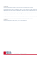
2.5.4 Receiver digital interface connector
The receiver is provided with an 8-pin waterproof plug for the digital communication interface, fitted to a 10 m long yellow cable
that is terminated in tinned wires.
Two communication modes can be selected, RS-232 or 4-wire RS-422 (default). The desired mode can be selected using the LAS MkII
configuration menu or by the control software.
Receiver digital interface connector and cable
For permanent connection to a computer always use optically or galvanicly isolated adapters or converters at the
computer serial port to protect against damage caused by lighting.
2.9 Installation and optical alignment
The alignment of the LAS MkII at the measurement site is an iterative process for establishing the optimum signal strength for
horizontal line-of-sight transmission. The different steps are summarized below. We recommend practicing the alignment
procedure at a short range (~ 250 m) before installation at longer distances.
The transmitter and receiver can be rotated around both vertical and horizontal axes. The coarse horizontal alignment (pan) can
be done by rotating the transmitter and receiver before the bolt(s) fixing the baseplate to the supporting structure is (are)
tightened. Fine pan adjustment is done with the two horizontal adjustment screws. For the vertical alignment (tilt) two vertical
adjustment screws are provided, one at the front and one at the rear.
2.9.1 Preparation for installation
Two people should carry out the alignment, one at the receiver and one at the transmitter. They must be able to communicate
either by radio, walkie-talkies or mobile telephones.
Note The final alignment should be carried out under conditions of clear or very clear visibility, i.e. visibility > 10 km.
The table below shows the typical variation in receiver signal strength over a path length of 3000 m for a nominal transmitter
power and receiver signal gain setting.
.
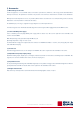
2.5.5 Receiver meteorological sensor kit connector
The 8-pin connector marked ‘Sensors’ must only be used with the accessory meteorological sensor kit. The 12 VDC
output must not be used to supply other equipment.
Receiver meteorological sensor kit connector
The accessory meteorological sensor kit is supplied pre-wired with a 10 meter long yellow cable and waterproof connector and
will be automatically powered and recognised when plugged into the LAS MkII receiver.
Do not connect a computer to the sensor connector using the digital interface plug and cable. The 12 V power
output for the sensors may damage the computer serial port.
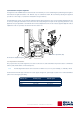
2.6 Aperture restrictors for short range applications
In case the LAS MkII is required to operate over short distances the aperture diameter of the transmitter and receiver can be
reduced to 100 mm using the supplied restrictors. The LAS MkII can then be used over path lengths from 100 m to 1 km.
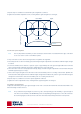
To fit the restrictors proceed as follows and shown in the diagram below:
1. Remove 3 of the 6 retaining screws of the transmitter and receiver windows
2. Replace the screws by the nylon spacers
3. Secure the restrictors using the M4 x 25 mm cap-head screws and nylon washers
When using the restrictors, remember to set the aperture values in the LAS MkII configuration menu to 100 mm.
As the beam diameter becomes smaller so does the beam divergence. This means that the alignment of the 100 mm
LAS MkII may be more critical than for the full-beam 150 mm LAS MkII. It is recommended to use very stable
mounting constructions.
2.7 Using the display and key-pad
The waterproof display and menu navigation keys located on the rear panel of the LAS MkII receiver allow for complete instru-
ment configuration and control without the need for additional computers, cables and software. This section describes the basic
procedure for navigating through the menus, changing and confirming settings.
Note The complete menu structure of the LAS MkII scintillometer can be found in Appendix C.
Navigating through the LAS MkII menu structure is very straight-forward using the keys.
The keys are used to scroll through the (sub-) menus or to select or enter a value:
Scroll mode:
Up key Select next menu item
Down key Select previous menu item
Left key Go one menu level back
Right key Select displayed menu item
Edit mode
Up key Increment digit
Down key Decrement digit
Left key Select previous digit
Right key Select next digit
Confirm (edit mode)
Display shows Confirm Entry - Yes
Up or down key Cycles through options; Yes, No, Quit
Right key Completes selected action:
Yes - confirm changes and go back to menu
No - cancel and go back to edit mode
Quit - exit edit mode without changes
.
For example to change the path length setting from 110.0 m to 1250.0 m the following actions need to be performed:
In order to keep this manual as concise as possible, this process will be shortened in the following way:
Main Menu → 2. Configuration → 1. Installation → 2. Path length → 1250.0 m → Confirm
Note To reduce power consumption and increase life-time, the receiver display is turned off if no keys are pressed for
4 minutes. Pressing any key turns the display on again.
2.8 Configuration for measurement
The table below shows the sub-menus contained within Menu 2, Configuration. These sub-menus require setting up before, or
during, installation. To configure the LAS MKII receiver before installation refer to the ‘power up receiver’ section 2.9.4.
Note The complete menu structure of the LAS MkII scintillometer can be found in Appendix C.
Note The Sensor sub-menu default values are used when the meteorological sensor kit is not connected. These values
can be changed by the user, within the ranges shown.
Note If a BaudRate is entered different to those listed, the receiver will select the nearest valid value.
Valid interface types are 232 and 422, if another number is entered the port will switch off.
.
2.8.1 Setting parameters to measure C
n
2
C
n
2
is measured using the following general algorithm:
Where; D is the aperture diameter of the LAS MkII, L is the distance between the transmitter and the receiver (the path length)
and σ
lnI
2
the measured variance of the natural logarithm of intensity fluctuations.
The parameters for aperture and path length must be set in the receiver.
Note Set the Aperture to the value stated on the Test and Final Inspection Certificate supplied with the instrument. The
typical setting is 149 mm.
2.8.2 Setting parameters to measure sensible heat flux
From C
n
2
data, together with wind speed, temperature, and an estimate of the topology and the displacement height; the surface
sensible heat flux (H) can be determined from by solving equations iteratively. See Appendix C for further information.
In addition to the parameters for measurement of C
n
2
the following additional parameters are required to measure surface sensi-
ble heat flux (H):
• Installation height
• Zero Displacement Height
• Bowen Ratio
• Temperature
• Pressure from meteorological sensor kit when connected
• Wind Speed
• Roughness Length
The surface sensible heat flux (H) can be calculated by a computer using the supplied EVATION software package, the data from
the LAS MkII and meteorological sensor kit and by inputting other parameters, such as the roughness length.
However, for most day-time (unstable) conditions and when the LAS MkII is installed relatively high above the surface (z
LAS MkII
> 20 m) the contribution of the friction velocity is relatively small. For these conditions the free convection method can be
applied.
Note that the free convection sensible heat flux (H
free
) calculated by this method is not as accurate as the standard method for H
because it does not allow for surface topography (roughness length, etc.).
See Appendix C for further information.
When the meteorological sensor kit is connected the LAS MkII can internally calculate and log the free convection sensible heat
flux (H
free
).
2.8.3 External sensors
When the meteorological sensor kit is connected the correct factory sensitivities and ranges are automatically selected.
When the kit is not connected, fixed values typical of the measurement location can be entered in sub-menu 3 of the configuration menu.
.
2.8.4 Data Logger
Configure the following data logger settings; date, time, sleep time, wakeup time, log-interval and send interval.
The wakeup time defines the start of the operational mode. When the operational mode is active the LAS is measuring and
logging data; the receiver heater is turned on when the temperature of the receiver is below the ‘operating temperature’ in the
heater menu.
The sleep time defines the start of the low power ‘sleep’ mode, during which there is no measurement and the receiver heater is
turned on only when the temperature of the receiver is below the ‘standby temperature’ in the heater menu.
The log interval defines the interval over which measurements will be averaged and then stored in the internal flash data memory.
The send interval defines the interval at which the current data values will be sent automatically to a computer.
2.8.5 Interface
Configure the following interface settings; baud rate, parity, data bits and interface type.
Green indicator function Status
Normal blinking
(0.2 sec on 0.8 sec off) The instrument is operational
Fast blinking
(0.2 sec on 0.2 sec off) A hardware error was detected
Slow blinking The boot loader is running
Always on The boot loader is halted,
no application is running
Always off The power is switched off,
the instrument has a hardware error,
or the supply voltage is too low
.
2.9.2 Installing the transmitter and receiver
1. Install the transmitter and receiver of the LAS MkII at their selected positions.
2. The bolts used to fix the baseplates to the tripods or other supporting structures are fastened by hand, so that the transmitter
and receiver can still be turned around their vertical axes.
3. Clamp the telescopes to the rails on the tops of the transmitter and receiver using the 4 mm hexagonal Allen keys. Note that
the telescopes are factory-aligned for each transmitter and receiver and are marked appropriately with either ‘Transmitter’
or ‘Receiver’.
4. Adjust the transmitter both horizontally (pan) and vertically (tilt) such that the crosshairs of the telescope are centred on the
receiver window. Tighten the bolt(s) fixing the baseplate to the supporting structures (further adjustments can be done with
the pan fine adjustment screws).
5. Carry out the same procedure for the receiver relative to the transmitter.
2.9.3 Power up transmitter
1. Connect a suitable 12 VDC power supply to the transmitter and switch on the power. The red power indicator on the transmitter
rear panel will illuminate.
2. Unscrew the cover of the power adjustment knob and initially set the 10-turn dial (scaled from 0 to 1000) to maximum.
2.9.4 Power up receiver
1. Connect a suitable 12 VDC power supply to the receiver and switch on the power. The green power and status indicator on the
rear panel provides information on the operation of the LAS MkII receiver, as in the following table.
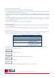
2. The display on the rear panel of the receiver will cycle through the following start-up messages (examples are shown):
• The serial number and production document
• The software release and hardware release
• The communication parameters (interface type, baud rate, data bits, parity)
• The successful start-up message
Or ‘Check 12V Heater’ (this is only a warning that the heater is not set, it is not an error)
.
If a hardware error message occurs, try turning off the power and the restarting the receiver. If the error persists,
make a note of the code and contact support@kippzonen.com
3. A configuration error message will be displayed if one or more of the configuration parameters stored in the memory are not
correct. The following configuration error messages are defined:
Note More detailed information about configuration errors and how to clear them is given in Appendix D.
1. At the receiver ensure that the LAS MKII is configured as described in section 2.8, in particular the path length, installation
height and aperture (100 mm or 149 mm).
2. At the receiver set the signal gain using the navigation keys as follows:
Main Menu → 2. Configuration → 1. Installation → 6. Signal Gain
Initially set the signal gain to 1 (this is the default value).
3. Return to the main menu and select
Main Menu → 1. View RealTime → 1. Signal Level
2.9.5 Transmitter optical alignment
Note It is very important to follow this procedure carefully because the data is not reliable when the edges of the beam
are to close to the receiver or transmitter aperture.
1. The person at the receiver observes the signal level and communicates the values to the person at the transmitter.
2. The person at the transmitter first slowly turns the transmitter horizontally (pan) left and right using the adjustment screws
until the maximum signal strength (as given by the person at the receiver) is reached.
3. There should be a ‘plateau’ region of approximately the same signal strength between the horizontal edges of beam. Find the
mid-point of this region, which will be the centre of the beam.
4. The transmitter then needs to be slowly adjusted vertically (tilt) up and down using the adjustment screws to find the mid-point
maximum signal strength, as in step 3.
5. The concept of the maximum signal ‘plateau is shown in the figure on the next page.
6. If the receiver signal strength is more than 200 % reduce the transmitter power for a reading of about 100 %. Optimise the
horizontal and vertical alignment for the maximum signal strength in the middle of the ‘plateau’ region. Each time the signal
strength is more than 200 % reduce the transmitter power for a reading of about 100 %.
.
7. Repeat steps 2 to 8 until the best transmitter optical alignment is achieved.
8. Tighten the transmitter adjustment screws, checking that the signal strength has not changed.
.
2.9.6 Receiver optical alignment
Note It is very important to follow this procedure carefully because the data is not reliable when the edges of the beam
are too close to the receiver or transmitter aperture.
1. The person at the receiver observes the signal level and optimises the alignment.
2. First slowly turn the receiver horizontally (pan) left and right using the adjustment screws until the maximum signal strength
is reached.
3. As for the transmitter, there should be a ‘plateau’ region of approximately the same signal strength between the horizontal
edges of beam. Find the mid-point of this region, which will be the centre of the beam.
4. The receiver then needs to be slowly adjusted vertically (tilt) up and down using the adjustment screws to find the mid-point
maximum signal strength, as in step 3.
5. If the receiver signal strength is more than 200 % reduce the transmitter power for a reading of about 100%. Optimise the
horizontal and vertical alignment for the maximum signal strength in the middle of the ‘plateau’ region. Each time the signal
strength is more than 200 % reduce the transmitter power for a reading of about 100%.
6. Repeat steps 2 to 5 until the best receiver optical alignment is achieved.
7. Tighten the receiver adjustment screws, checking that the signal strength has not changed.
2.9.7 Finalise optical alignment
1. Adjust the transmitter power to give signal strength of 100 - 120 % and lock the knob with the small black tab. Make a note
of the dial setting for future reference.
Note It is possible that at path lengths of 3000 m or greater, and depending upon the visibility, a signal strength of
100 - 120 % is not achievable. The LAS MKII will operate correctly with signal strength of 25% or more. Do not increase
the receiver signal gain, as this also increases the noise and overall measurement performance is not improved.
.
2. Screw on the cover of the power adjustment knob. Hand-tighten only to avoid damaging the o-ring seal.
3. The optical alignment is now complete. Go back to the View RealTime menu and sub-menu 3 (C
n
2
). The LAS MkII should now
be measuring and logging data according to the configuration set in section 2.8.
.
Note It is possible that the transmitter or receiver is not now aligned with the centre of the crosshairs of its telescope.
This is due to a difference between the operating path length and the range at which the telescopes were adjusted
at the factory. Therefore never rely only on the telescopes during the alignment procedure! If desired, the crosshairs
of the telescopes can be adjusted using the instructions provided with them.
4. The telescopes can now be removed and the sun shields fitted to the transmitter and receiver with the fixing screws and the
3 mm hexagonal Allen keys. Store the telescopes carefully for future use.
Never (re-)align the LAS MkII transmitter and receiver using the telescopes only and do not swap the transmitter
and receiver telescopes. Always use the optical alignment procedure.
To avoid non-linearity of the detector and overload of the electronics, the signal strength is limited to a maximum
of 250 %. Above this the over-range value of 999 % is shown.
LASRX 12:0001
120-0371500-4
SOFTW.REL 2.00
HARDW.REL 1.2
COM1 - RS422
4800/8/N
Start Completed
NO ERRORS