
Owner's manual


11
Connector for main battery – the user can connect any type of battery (ZnMn, alkaline, NiCd,
NiMH, lithium, Pb accu, solar panel, mains adapter) with output voltage in the range of 4Vdc
– 20Vdc.
LED jumper – when jumper is closed, LED diode will indicate the operation. For maximum
power savings open the jumper. The LED indicates also when communication with SD card
can be performed. So, if LED is on, do not manipulate (remove or insert) SD card.
Otherwise, data could be either lost or partially damaged.
If the SD card is not used it should be removed to extend battery life.
Relay output RE+ and RE- – this is optically isolated polarized solid relay output, primary
used for switching external devices. These contacts can be used for switching power
supplies for external sensors that do not share a common ground with the LOGBOX SD.
The relay contacts are normally open and close during measurement interval. The LOGBOX
SD then takes after the programmed delay a measurement. After that the relay opens again
to switch off the sensor and limit the power consumption.
The relay can handle 60 VDC @ 300 mA.
PWR OUT output – switched battery output for powering local sensors or instruments.
VREF output – switched reference voltage of 2.5V for bridge or similar instruments.
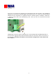
The instrument is mounted in a plastic enclosure (IP65 protection class) allowing outdoor
installations. For smaller measuring systems it is possible to use 4 pieces of AA battery
(mignon) inside the battery compartment which is attached to the lid of the enclosure. This
results in a compact and portable solution of the LOGBOX SD.
The electronic design of the LOGBOX SD allows precision measurements with high
resolution. For this purpose it is equipped with two types of analog to digital converters.
They differ in resolution (12 bits or 24 bits), configuration options, speed of conversion and
applications for which they are used. Inputs for both converters are physically the same and
are configured by the software. It is possible to setup 8 unipolar inputs or 3 differential
inputs and 2 unipolar inputs or combinations.
Data logger has one ground potential (referenced to power supply GND. There are three
connectors with GND potential – all are internally connected and allow comfortable
connection of battery, RS232 serial line and analog and digital inputs.
For setting up configuration of analog inputs there are few basic rules.
The highest priority is for 24 bits differential measurements, then 12 bit single ended
measurements. Depending on priority it is necessary to configure analog inputs from AIN1
to AIN8. Practically it means that if the user wants to measure differential signal with 24 bits
resolution, this input must be located on AIN1, AIN2 (pair). If the user wants to measure two
differential inputs, they must be located on AIN1, AIN2 and AIN3, AIN4 (pairs). Only after the
differential inputs there can be single ended 12 bit resolution inputs (if any).
Digital inputs can be configured for measuring frequency, time (when digital input is in high
logical state) or as a counter. After defining polynomial coefficients of the 3-rd order it is
converted to engineering units. The advantage is that measuring of digital inputs is active
also during sleep time (during whole period of logging). That means if logging is configured
every minute, frequency represents mean value over one minute. If it is configured as
counter, it will measure number of counts per one minute and if it is configured for time
measurement, it represents number of seconds when input was in logical high level over one
minute. The same applies to all logging intervals over one minute.
With logging intervals of 10s, 20s and 30s only counter and time options are available.