Skyradiometer POM-01 / POM-02 Operation Manual (Windows OS) October 19, 2009 PREDE Co., Ltd. Head Office: 1117, Kusabana, Akiruno-shi, Tokyo, 197-0802, Japan Research Center: Sasamoto Blg, 1-26-8, Kamidaira, Fussa-shi, Tokyo, 197-0012, Japan TEL+81-42-539-3755 FAX:+81-42-539-3757 URL: http://www.prede.com/ E-mail: sales@prede.
Specifications <POM-01> Half view angle Min scattering angle 0.5° 3° Band width 50% 10nm Channel Wavelength Wavelength 1 2 3 4 5 6 315 400 500 675 870 940 ※ Channel 0 is dark reference 7 1020 (nm) 940nm is channel for water vapor Channel setting Filter foil type Detector Si photodiode Range 2.5mA ,250uA ,25uA ,2.5uA ,250nA ,25nA ,2.5nA Temperature control 35℃ Tracking control Stepping Motor :2 way, Azimuth and Zenith , Stepping angle:0.
Installation Installation step guide It is recommended to let a first installation in clear day. Sun sensor can not be active under cloudy sky and that cause the insufficient tracking accuracy. 1) Mount sun tracker on solid and flat place with free field of view especially toward East – South – West direction. Make sure label “S” at tracker bottom looks toward South. For data transfer and power supply a maximum distance of 30m to the PC and power supply are allowed.
5) Connect the rain sensor. 6) Connect the cable ④,⑤,⑦ and the sun sensor ⑥. Assemble all cables into mesh cover not to tangle. 7) Connect the communication cable(RS422) and then the power cable(AC3P). Immediately after connecting power cable, tracker starts origin searching. Be careful of the rotating tracker and obstacle around its rotating area. If tracker doesn’t start rotating performance, it means there is any cable connection lack or mechanical trouble.
8) After stop tracker rotating, prepare the PC setting to start measurement. 9) See page XX and edit the measurement schedule and system construction (filter setting). Measurement can start with pressing “OK” on the screen. * Tacking Mode (Calculation mode and Sun sensor mode) Skyradiometer can track sun position with auto-switching calculation and sun sensor mode. Based on the data (latitude, longitude, time) it can keep sun tracking. This is the so called calculation mode.
Installation check This step is required after first installation. After start of measurement, open “Manual Operation” and carry out next installation check. * Installation accuracy can affect value of direct sun measurement. Especially in the early morning, sun sensor can't respond even when it is clear sky because sun light is very weak. Skyradiometer performs with calculation mode. Then as sun altitude is increasing with time, Skyradiometer can perform with sun sensor mode.
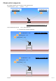
Setting Required specifications PC:Pentium2< Memory 256MB<, Free HDD area 1GB<、Serial port(RS-422) OS:Windows XP / Vista Click “Skyradiometer2009.exe” Start window(Fig1) After 10 seconds, measurement auto-start.
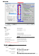
Setting screen POM-01 available ※1 POM-02 available Please fill in the field. General Model : POM-02 or POM-01 Skyradiometer S/N : Serial number PS******* Sun Tracker : Serial number PS******* Place : Latitude [deg] : Three places of decimals Longitude [deg] : Three places of decimals Data path : It is necessary to specify new path to data directory. Important: User needs to create sub-directory on your hard disk.
Observation Setup Observation Starting/Ending Airmass : Observation Switching Airmass Airmass to switch the way of measurement ※1 : Scattering Measurement for Aerosol Observation : If user do not select, skyradiometer perform only direct sun measurement.
Observation sequence Skyradiometer operates during airmass is under registered value. 1. observation start (end) : Airmass <= 10 Start Airmass<=10 End Airmass>=10 Example.Observation Starting/Ending Airmas =10 2. Aerosol observation interval : Time or (Every 10minute) Airmass (Every 0.25 step or 20minute) 3rd observation --- 9:20 Example. Time / Every 10minute 2nd observation --- 9:10 1st observation --- 9:00 3rd observation --- 4.00 Example. Airmass / Every 0.25 2nd observation --- 4.
4. : Scattering direction Skyradiometer steps clockwise (morning) and counterclockwise (afternoon) while sun altitude is below 75deg. Skyradiometer steps to zenith direction while sun altitude is over 75deg.
Disk scan schedule : interval day and time are editable(Default : every 7day, 10:00AM) Disk scan is executed at schedule for selected wavelength on the condition sky is clear (sun sensor threshold). Time proofreading for tracker : 23:00 Clock built-in tracker adjust PC time. Rain sensor : Skyradiometer stops sun tracking and remains at waiting position downward. Waiting position is direction south and altitude −30deg.
■ Both Side Every aerosol observation, skyradiometer scan at both direction. ■ Alternation Every aerosol skyradiometer observation, changes the scattering direction alternately.
Operation screen Main screen あ Main screen display ◆Status LT : Local time UTC : Universal time coordinateded Azimuth angle : sun azimuth calculated from PC clock (East:−90°South: 0°West: +90°North: 180°)calculated position / real position Altitude angle : sun altitude calculated from PC clock (Nadir: −90° Horizon: 0° Zenith: 90°) calculated position / real position Airmass : airmass calculated from PC clock Next observation time : scheduled next observation time and airmass Monitor chann
Button guide Monitor channel setting : User can select monitor channel ※ Return to Dark after aerosol and direct sun observation. ・Azimuth scan : Aerosol measurement ・Sun-Disk Scan : Disk scan with all wavelength ・Dark∼CH11 Manual Operation data stored at each wavelength folder ・X-scan : scan (0.1 ° step)along horizontal and vertical direction from the center(sun) ±1°area. Center of gravity is indicated at bottom line. Value within 0.030 is best for optical axis (alignment).
Aerosol observation graph Display a graph of aerosol measurement with all wavelength. X-axis is scattering angle. Unit is ampere (Log scale). Type : Line chart X-axis : Scattering angle [deg]:0(Min)∼180(Max) Y1-axis (POM−01): 400nm,500nm,675nm,870nm,940nm,1020nm [A] [Log] (.POM−02): 340nm,380nm,400nm,500nm,675nm,870nm,940nm,1020nm 1627nm,2200nmk[A] [Log] Y2-axis : 315nm [A] [Log] Upper right corner shows real time value at scattering angle and bottom shows time record.
Direct sun observation graph Display a graph of direct measurement thorough a day. Unit is ampere (Log scale). Type : Plot type X-axis : Time Y1-axis (POM-01) : (POM-02) : [Local time] 400nm,500nm,675nm,870nm,940nm,1020nm [A][Log] 340nm,380nm,400nm,500nm,675nm,870nm,940nm,1020nm, 1627nm, 2200nm [A][Log] Y2-axis : 315nm[A][Log] Upper right corner shows real time value and bottom shows time record.
Manual Operation This window is enable user to operate sun tracker and sensor manually. 青 枠 : Send command directly. Response is seen at Receive Data area. 緑 枠 : Operate the direction of sensor manually. Angle is Absolute angle. (0.0, 0.0:South, Horizon) Offset calibration : receive offset for 7 gains and the result on receive data area. Measure :Tracker direct position at selected position (Azimuth, Altitude) and execute measurement. 黄 枠 : Operate the direction of sensor manually.
Data format Skyradiometer create four kinds of data file as follows; 1.Aerosol obsevation … FileName : yymmddnn.dat 2.Direct sun observation … FileName : yymmddnn.sun 3.Disk scan data file … FileName : yymmddnn.V** 4.Cloud scan data file … FileName : yymmddnn.cld ”yymmdd” yy:year mm:month dd:day nn:file number(00∼99). Common header A common header is added with two lines of each observation data file. 【Contents】 1st line: POM Type(6) ,Tracker No.(7) ,Sensor No.
※Measure type S: Direct sun measurement 2nd line: Time(UTC) ,Time(Local Time) ,azimuth angle ,zenith angle , Data(Ch1)、Data(Ch2) …… Data(Ch10) ,Data(Ch11) ,NIR temperature ,housing temperature, Barometer,Sun sensor level ・azimuth angle and zenith angle is motor position. ・Unit of data is ampere. ※Without barometer installed, com is selected, data record 0000 / com is not selected, data record -999. 3.Disk scan data file File name:09052600.
・Azimuth angle and zenith angle is motor position. ・Unit of output data is ampere. ・Data is recorded as scattering angle order. ※ Without barometer installed, com is selected, data record 0000 / com is not selected, data record -999. User Maintenance Before maintenance, please end the operation program and disconnect power cable. ・Silica gel replacement There is silica gel case under cable connector. Remove that and if color is changed pink, replace with new one.