Abso Charger 12V 20A (AC1220) 12V 40A (AC1240) 12V 60A (AC1260) 24V 30A (AC2430) Owner’s Manual
For safe and optimum performance, the KISAE Abso Charger must be used properly. Carefully read and follow all instructions and guidelines in this manual and give special attention to the CAUTION and WARNING statements. PLEASE KEEP THIS MANUAL FOR FUTURE REFERENCE Disclaimer While every precaution has been taken to ensure the accuracy of the contents of this guide, KISAE Technology assumes no responsibility for errors or omissions.
Table of Contents 1. INTRODUCTION .................................................................................................... 4 2. PRODUCT DESCRIPTION ........................................................................................ 5 3. UNDERSTANDING THE UNIT .................................................................................. 5 4. INSTALLING THE CHARGER .................................................................................... 9 5. UNIT OPERATION ..........
1. INTRODUCTION Thank you for purchasing the KISAE Abso Charger. With our state of the art, easy to use design, this product will offer you reliable service by providing a multi-stage multi-bank battery charger to charge different types of batteries you have installed in your boat, RV, vehicle or your cabin battery bank. An innovative feature we offer is the ability to charge your main battery bank as first priority so that you may charge this main bank quickly.
and must not be played with. • The child does not try to charge non-rechargeable batteries because of the danger of eruption. • Examine the battery charger regularly for damage, especially the cord, plug and enclosure. If the battery charger is damaged, it must not be used until it has been repaired. FCC INFORMATION This equipment has been tested and found to comply with the limits for a Class B digital device, pursuant to part 15 of the FCC Rules.
Silent Mode: A unique feature of the KISAE Abso Charger is the ability to disable the cooling fan for total silent operation at night or whenever required. This setting is manually activated via the display and remains active for a period of 12 hours, or unit manually deactivated. Please note that charger output will be reduced while in Silent Mode, leading to longer required recharge times. When the Silent Mode is activated, the ‘Auto’ icon is show on the Digital Display.
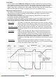
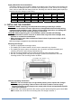
AC Output Wiring Compartment DC Output fuses AC Input Wire Strain Relief Digital Display Port Battery Temperature Sensor Port Unit GND Battery Pos Battery Neg (Bank 1) (Common) Battery Pos (Bank 2) Battery Pos (Bank 3) Picture shown AC1260 model Typical wiring block diagram of the Battery Charger with 3 batteries bank: AC Source: (90-265Vac, 50Hz/60Hz) Branch Breaker Battery Pos: Bank 1 Battery Bank 1 (Main Battery) Battery Pos: Bank 2 Battery Bank 2 (Jump Start Battery) Battery Pos: Bank 3 Batte
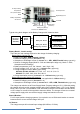
Digital Display Port: The Digital Display Port has dual functions. It can be used for optional external display or for PC interface. Use for external display The interface port is used for connecting an optional external display. The external display (sold separately) has identical functions to the built-in unit display. Use for PC interface • A KISAE Abso Charger PC Interface Kit (sold separately) is available and is used to connect between the port and the PC.
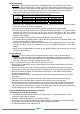
Battery Bank Size Recommendation: The battery charging current rating is based on the battery size. Each battery bank should meet the minimum Ah rating as shown. If a smaller size battery bank is used, set the current rating to lower value to match with the battery bank size. Normally, the minimum battery bank capacity is based on twice the charger current rating.
DC Output Wiring: WARNING: The DC wiring used must be of appropriate size. An individual over-current protection device usually within 7 inches (17.8cm) of each battery bank is required. A DC disconnect switch is also recommended. Both devices must be rated for DC voltage and current and be rated to withstand the short circuit current available from the connected battery bank. Both devices must match with the size of the DC wiring.
Note: Do not use COM_2 on the Remote Display. For AC2430 model: The 24V model is capable to connect in parallel. Connect two AC2430 in parallel will provide a total of 24V 60A charging current. Use on single AC2430 charger • To install the optional Remote Display in a specific location, a 6 pin standard RJ12 cable (maximum length 25 ft) is required. • Install the standard RJ12 cable in your desired location.
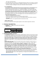
Test the Charger Connection: • Switch AC branch breaker switch to ON. • The display will turn on. Pressing the ‘INFO’ key will toggle the display to show the factory default setting. The charger is now ready to use. 5. UNIT OPERATION Understanding the Charging Mechanism • The charger is a three bank battery charger that is capable of charging a maximum of three battery banks. • The charger is designed to have Bank 1 charge the main battery bank.
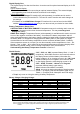
Understanding the Digital Display Function with no AC Input: Press and hold the ‘INFO’ key for 3 seconds to check all the three battery banks voltage so as the charger revision. Understanding the Function Key ‘INFO’, ‘NEXT’ and ‘SET’ during Charger Setting: ‘INFO’: Press and hold the key for longer than 3 seconds to enter charger setting mode and show function setting. Once new setting is done, press ‘INFO’ again to exit the charger setting mode.
Procedure to set or view charger setting: Follow the procedure or sequence in Appendix A1 and A2 to set or view the charger setting.
Procedure to Equalize Flooded Battery: DANGER: Explosion Hazard. The battery generates explosive gases during equalization. Follow all the battery safety precautions listed in the manual. DANGER: Explosion Hazard and Risk of Battery damage. When using the equalization mode, the user has to be sure the battery connected to the channel is a flooded battery type. Equalizing a non-flooded battery may overcharge the battery and may cause the battery to explode. CAUTION: Risk of Battery and Equipment damage.
will recover automatically back to maximum charging current when the environmental temperature drops to below 45°C. Over Temperature Shutdown: When the charger senses the environmental temperature is above 60°C, the charger will shutdown. It will recover automatically when the environmental temperature drops to below 45°C. Battery Reverse Polarity: When a reverse polarity is connected to the battery bank, Fault Code E03 on display will appear.
6. SPECIFICATIONS AC1220 AC1240 AC1260 AC2430 20A 40A 60A 30A Charger Output: Output Current (Maximum) Output Voltage Range: Charge Float Equalize Charging Control 14.2 - 15.5 V 28.4 – 31.0 V 13.4 - 13.8 V 26.8 – 27.6 V 16.0 V 32.
7. WARRANTY One Year Limited Warranty The limited warranty program is the only one that applies to this unit, and it sets forth all the responsibilities of KISAE. There is no other warranty, other than those described herein. Any implied warranty of merchantability of fitness for a particular purpose on this unit is limited in duration to the duration of this warranty.
Page 19
Page 20
Appendix B Page 21