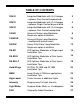
TABLE OF CONTENTS 20W-D Integrated Modulator with G-4 Halogen - replaces Dual Contact bayonet bulb 2 20W-S Integrated Modulator with G-4 Halogen - replaces Single Contact bayonet bulb 4 30W-D Integrated Modulator with G-4 Halogen - replaces Dual Contact wedge bulb 6 100HD Universal Brake Lamp Modulator Single wire splice Installation 8 100HD-M Universal Brake Lamp Modulator - modified with ballast circuit 10 200GW Heavy-Duty Brake Lamp Modulator Single wire splice Installation 12 25LED LE
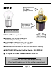
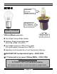
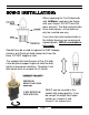
20W-D Replaceable G-4 Bi-pin Halogen element Microprocessor fully integrated in the bulb-base DIRECT PLUG-IN Bayonet Base Dual Contacts 20W-D tailBlazer application Replaces Dual-contact bulb types: GE #1157 (12V 32/3cp) G-4 Halogen element is 20W (14.5 v) rated 320 Lumen output.
20W-D INSTALLATION: When replacing the Tail/ Brake bulb with tailBlazer, grab only the flange with your fingers. DO NOT twist the glass element. The dual contact bulbs have indexed pins, so the bulb can only be inserted one way. If you have twin dual-contact bulbs in the taillight housing, we recommend replacing both. 20W-D is available in twin-pack. Should there be a need to replace the 20W Halogen element, pull the bi-pin bulb straight out from the base. DO NOT wiggle or twist.
20W-S Replaceable G-4 Bi-pin Halogen element Microprocessor fully integrated in the bulb-base DIRECT PLUG-IN Bayonet Base Single Contact 20W-S tailBlazer application Twin Single Contact Bulbs taillights Replaces Single-contact bulb types: GE #1156, #1030 (12V 32CP) G-4 Halogen element is 20W (14.
20W-S INSTALLATION: When replacing the Brake bulb with tailBlazer, grab only the flange with your fingers. DO NOT twist the glass element. The single contact bulbs have non-indexed base, so the bulb can be inserted in any orientation. Please identify which of the two bulbs is for the brakes. Replace the brake bulb only. 20W-S is available in twin-pack. Should there be a need to replace the 20W Halogen element, pull the bi-pin bulb straight out from the base. DO NOT wiggle or twist.
30W-D Replaceable G-4 Bi-pin Halogen element Microprocessor fully integrated in the bulb-base DIRECT PLUG-IN Wedge Base Dual Contacts 30W-D tailBlazer application Replaces Dual-contact bulb types: GE #3157 (12V 32/3cp) G-4 Halogen element is 20W (14.5 v) rated 320 Lumen output. Average life is 2000 hrs Modulates the Brake bulb for a 4-sec Deceleration Warning 5 MATCHED SET for dual bulb tail lights – 30W-D 2PAK HANDLING PRECAUTION: EXTREMELY HOT! Let it cool before handling.
30W-D INSTALLATION: When replacing the Tail/ Brake bulb with tailBlazer, grab only the flange with your fingers. DO NOT twist the glass element. The dual contact bulbs have indexed pins, so the bulb can only be inserted one way. If you have twin dual-contact bulbs in the taillight housing, we recommend replacing both. 30W-D is available in twin-pack. Should there be a need to replace the 20W Halogen element, pull the bi-pin bulb straight out from the base. DO NOT wiggle or twist.
0HD (1) WIRE SPLICE-IN tailBlazer 100HD has (3) screw-in terminals: Input Terminal: for Brake Input Output Terminal: for Output to the bulbs Ground Terminal: for the Ground Modulates the Brake bulb for a 4-sec Deceleration Warning Trigger voltage: 10.9 volts 100HD can handle up to (3) brake light bulbs, which are typically 25 watts each. If you have additional lights or plan to add them, we highly recommend our heavy-duty unit – 200GW. DO NOT EXCEED THE RATED WATTAGE.
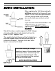
100-HD INSTALLATION: On most models, access to the brake wire is possible by removing the taillight assembly, or simply by removing the seat and following the rear of the taillight housing for appropriate brake wire and ground wire. For twin bulb type of taillight arrangements, there’s typically a “Y” harness before it is split. In order to modulate both bulbs together, the correct location for the splice is upstream of the “Y” harness.
100HD-M (1) WIRE SPLICE-IN tailBlazer 100HD-M has (3) screw-in terminals: Input Terminal: for Brake Input Output Terminal: for Output to the bulbs Ground Terminal: for the Ground Modulates the Brake bulb for a 4-sec Deceleration Warning Trigger voltage: 10.9 volts 100HD-M has a modified ballast circuit to allow monitoring voltage pass-thru. This allows bulb filament detection. If your bike has dash warning that indicates burned-out brake bulb, this unit is the correct application.
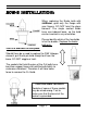
100HD-M INSTALLATION: This is a modified unit for installation on bikes with brake bulb monitoring. For twin bulb type of taillight arrangements, there’s typically a “Y” harness before it is split. In order to modulate both bulbs together, the correct location for the splice is upstream of the “Y” harness. Once you have identified the brake wire and chosen the correct location to make the splice, cut and prepare the wire ends as shown here.
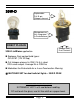
200GW (1) WIRE SPLICE-IN tailBlazer 200GW has (3) screw-in terminals: Input Terminal: for Brake Input Output Terminal: for Output to the bulbs Ground Terminal: for the Ground Modulates the Brake bulb for a 4-sec Deceleration Warning Trigger voltage: 10.9 volts 200GW can handle up to (4) brake light bulbs, which are typically 25 watts each. If you have a trailer with more than (2) bulbs, it will exceed the rated wattage. Max Load is (6) x25W or 150W DO NOT EXCEED THE RATED WATTAGE.
200GW INSTALLATION: This is a heavy-duty unit designed to handle up to (4) brake bulbs. On most models, access to the brake wire can be found under the seat. Please follow the electrical circuit diagram of your model and use a voltmeter to identify the correct wire and the proper location to splice-in. For most multiple bulb type of taillight arrangements, there’s typically a connector in the harness before it is split-up to feed different bulbs.
DIRECT PLUG-IN OUTPUT 25LED 25LED unit is for a single input split voltage operation. Honda Gold Wing SE models are equipped with the Spoiler LEDs that function with this special unit. Polarized Input Plug Output Pins are protected 6-volt operation for low intensity running lights Modulates for a 4-sec Deceleration Warning with brakes applied (Trigger voltage: 10.9 volts) Please Note! If the OUTPUT pins feel too lose, spread them a little so that the connection is snug.
25LED INSTALLATION: This is a special unit designed for a split voltage input of 6 volts for low intensity running light and 12 volts step-up for the brakes. 25LED modulator fits the OEM Wing-light for the GL1500 SE models. 25LED can be plugged in-line with the connector on the back of the trunk lid as shown. Use Velcro strip to mount it. 2-pin input connector is polarized to match with Gold Wing 1500 wiring. The output pins are protected internally, so reverse connection will not harm the electronics.
OUTPUT 25LED-D DIRECT PLUG-IN 25LED-D unit is for a Dual Input operation. Accessory input of 12-volts is required to power the unit.. Polarized Input Plug Output Pins are protected Insulation Displacement Connector (IDC) allows taping into a wire without cutting. It must be squeezed tight with pliers. The slot on its side is used to slip the small ring eyelet in for connection. Please Note! If the OUTPUT pins feel too lose, spread them a little so that the connection is snug.
25LED-D INSTALLATION: GOLD WING GL-1800 This unit has matching connectors for the Honda Gold Wing GL-1800. The inner plastic liner has to be removed to gain access to the 2-pin connectors of the LED spoiler. Plug the unit in-line and attach it with the Velcro pad supplied. The accessory input wire MUST BE connected to supply power to the unit. The trunk latch-release (18pin) connector is a good place to tap into. The Light Green wire with Black stripe is s suitable source.
OUTPUT 25LED-LT DIRECT PLUG-IN 25LED-D unit is for a Dual Input operation. Accessory input of 12-volts is required along with a separate input for the brake signal. Polarized Input Plug Output Pins are protected Insulation Displacement Connector (IDC) allows taping into a wire without cutting. It must be squeezed tight with pliers. The slot on its side is used to slip the small ring eyelet in for connection.
25LED-LT INSTALLATION: BMW K-1200LT This unit has matching connectors for the BMW K-1200LT. The lower cover and the mirror have to be removed to gain access to the 2-pin connector of the LED light-bar. Plug the unit in-line and attach it with the Velcro pad supplied. The accessory input wire MUST BE connected to supply power to the unit. Accessory input wire needs to be routed for the connection. Feed it through the opening towards the back of the passenger backrest.
Goldwing tailBlazer Application GL1800 w/Spoiler LEDs 25LED-Dual GL1800 200GW GL1500 SE w/Spoiler LEDs 25LED GL1500 200GW GL1200 and older 100HD or 20W-D Goldwing 1800 INSTALLATION: The new release 25LED-Dual with embedded microprocessor now allows programmable Running Light intensities. The unit is designed for dual inputs. It is a plug-in unit, which mounts on the back of the trunk lid.
Goldwing-1500 INSTALLATION: 25LED is a special unit designed for the GL-1500 SE models with OEM Spoiler LEDs. It operates with a split voltage supply of 6v/12v. It’s mounted on the back of the trunk lid with 2-pin plug-in connector. 200GW is also redesigned with embedded microprocessor. This unit is a (1) wire splice, and 25LED 200GW it mounts under the seat. To splice-in, locate the left-side 25pin connector under the seat. The brake wire to splice-in is: Dark Green w/Red Stripe.
BMW K1200LT ALL CAN-bus models Earlier models tailBlazer Application (2) 20W-DZ OR 25LED-D 20W-S 2PAK or 20W-DZ 20W-S, 20W-D or 100HD-M BMW K-1200LT 25LED- LT 20W-DZ 2PAK For the Rack mounted LED Light-bar, 25LED-LT is an in-line plug-in unit. It requires a connection to a switched power source. 25LED-LT also makes the Light bar to come on as a Running Light with programmable intensities. This feature improves your rearward visibility – especially since the Light bar is mounted so high off the ground.
BMW: K1100LT, RT series & Older models Access for (2) wing-nuts here 20W-S or 20W-D On most 1100 models, the taillight assembly has (2) single contact bulbs. Replace the top mounted brake bulb with 20W-S tailBlazer. Note! On models with the “Lamp Check” circuit, use ‘Z” version. POLARITY CHECK: If the tailBlazer fails to execute the 4-sec flash pattern upon applying brakes, check for correct polarity of the socket.
INTENSITY ADJUSTMENT: 2 tailBlazer circuitry utilizes a microprocessor with an e prom to memorize different settings for the TAIL LIGHT brightness. The BRAKE LIGHT brightness is always the maximum possible. The factory setting is for High Intensity.
SELECTING HIGH POWER BULBS: If you elect to replace your original tail or brake light bulb with a brighter bulb, there are a few things to consider: POWER CONSUMPTION: Motorcycles do not have large capacity batteries or heavy duty charging systems. HEAT GENERATION: High heat can damage plastic taillight housings or melt the wiring and sockets designed to handle lower temperatures. BEAM PATTERN: Different bulbs have different beam patterns.
AUXILIARY LIGHTS: If you already have additional lights or if you plan to add some, consider how the total wattage or the load (measured in Amps) will impact the primary fuse of the brake circuit. After that, select an appropriate model of tailBlazer for your application. Incandescent Lamps: Typical auxiliary lights for use as additional marker lamps have a single input. You chose to hook them up as Tail or Brake lights. The average wattage can be from 5 to 20 watts.
FREQUENTLY ASKED QUESTIONS: Q: 20W-D doesn’t plug in properly in the socket. What should I do? A: The integrated 20W-D unit has an indexed bayonet base, so it can only be inserted with correct orientation. Refer to diagram on page-3 to see how the pins are indexed. If the base feels too tight to be able to twist-in, you may have to file the solder bumps a little to reduce interference.
Q: I have hooked-up the 100HD and when I apply the brakes there’s no flashing, only a high frequency flicker. What’s going on? A: Refer to page-10 for proper connections. Reversing the input/output will not damage the unit but the flash pattern will be inhibited. Note! All splice-in tailBlazer models have the same polarity. Q: I have hooked-up 100HD. When I apply brakes, nothing happens. What’s wrong? A: The unit must be grounded to a good chassis ground.