TM TM Load Disc LD3 /LD360s Installation Manual CAUTION It is essential that all instructions in this manual be followed precisely to ensure proper operation of the equipment.
NOTICE The content of this document is the intellectual property of Kistler-Morse. Any reproduction or translation of this document without the written authorization of a Kistler-Morse officer is prohibited. CAUTION Follow these rules if welding is done on the vessel after installation of the Load Disc. The electrical current of the welder may pass through the Load Disc, causing damage to the transducer and possibly to the signal processor. To avoid damage, follow these precautions: 1.
Table of Contents Table of Contents Introduction ...................................................................................................i Welcome ........................................................................................................................................................... i About this manual ............................................................................................................................................ i Manual Conventions ...............
Table of Contents
Introduction Introduction This chapter describes the organization, manual conventions, and provides specification information. Welcome This manual describes the installation of the Load Disc load cell and its various hardware options. It includes procedures for leveling and shimming of the vessel if it is neccessary. Instructions for wiring the load cell to the junction boxes and wiring the junction boxes together and to the signal processor are also included.
Introduction Specifications LD3 LD360s Mechanical Compression Tension Shear Functional Integrity 4 x Rated Load 1 x Rated Load 0.5 x Rated Load 2 x Rated Load (compression) 4 x Rated Load 1 x Rated Load 0.5 x Rated Load 2 x Rated Load (compression) Electrical Excitation Voltage Impedance Maximum Current 10-14 VDC 7.5K Ohms±1% 3mA @ 12 VDC excitation 10-14 VDC 7.
Chapter 1: Description of the Load Disc Chapter 1: Description of the Load Disc This chapter describes the Load Disc Compression Load Cell and its installation options. Introduction The Load Disc is a low profile load cell that is bolted to both the support surface and the vessel supports, and is used to measure the weight of materials in vessels and tanks.
Chapter 1: Description of the Load Disc Installation Option Descriptions This section will briefly describe the following hardware options for the Load Disc: Universal Top Plate Adapter, Leveling Top Plate Adapter, Anyadapter Plate and Leveling Base Adapter Plate. See Chapter 2 and 3 for more specific installation instructions and refer to the TI drawings located in Appendix D. Universal Top Adapter Plate This option consists of the Universal Top Adapter Plate, spring washer and a hex head bolt.
Chapter 1: Description of the Load Disc Leveling Top Plate Adapter (1,000 - 7,500 lb capacity ONLY) This option consists of the Universal Top Adapter Plate, a hex head bolt, spherical washer set and jam nuts. The adapter plate attaches to the load disc with the hex bolt and hardware. The adapter plate then bolts to a vessel gusset or a flat plate welded to the vessel leg, using customer-supplied hardware.
Chapter 1: Description of the Load Disc Leveling Base Adapter Plate This kit consists of a Leveling Base Adapter Plate and four hex bolts, flat washers, and lock washers. The Load Disc bolts onto the leveling base adapter plate. This plate rests on four leveling nuts and washers screwed onto anchor bolts installed in the foundation. By turning the leveling nuts, the height of the load discs and thus the vessel, can be adjusted for proper load distribution.
Chapter 2: Preparing for the Load Disc Installation Chapter 2: Preparing for the Load Disc Installation This chapter describes the pre-check procedures for the Load Disc. Checking the Load Discs before installation will ensure properly working equipment that will provide accurate monitoring of vessel contents.
Chapter 2: Preparing for the Load Disc Installation Prepare Installation Equipment (Customer Supplied) The following equipment is needed to install Load Discs: Lifting equipment Tape measure Level Pry bar Marking pen Wrenches ASTM A-325 bolts (or equivalent strength), lock washers, and flat washers to secure Load Disc to vessel support (if applicable)* ASTM A-325 (or equivalent strength) anchor bolts, lock washers, flat washers, and nuts to secure Load Disc to vessel foundation (if applicable)* KM Test Me
Chapter 2: Preparing for the Load Disc Installation Factors That Affect Performance An independent, isolated vessel with no connection to any other vessel or adjacent structure provides the most accurate results for a weight measurement system. Examples of this type of application are floor scales and truck scales. Connections to other vessels or structures affect accuracy because the transducers interpret strain changes caused by the connecting structures as being caused by changes in the material weight.
Chapter 3: Mounting the Load Disc Chapter 3: Mounting the Load Disc This chapter describes installation and wiring of the Load Disc and junction boxes. Follow all instructions carefully to ensure proper operation of the system. General Information The Load Disc has a variety of mounting hardware options that accommodate almost all possible applications.
Chapter 3: Mounting the Load Disc Load Disc General Installation This section describes the Load Disc installation procedures for the following hardware options: Universal Top Plate Adapter, Leveling Top Plate Adapter, Anyadapter Plate, and Leveling Base Adapter Plate. 1. Prior to installing the Load Discs, verify that they are the correct capacity for your application by reviewing the information engraved on the Load Disc baseplates. 2.
Chapter 3: Mounting the Load Disc 7. 8. 9. Inspect the foundation and vessel mounting surfaces that will mate to the Load Disc plates. a. Check the mounting hole locations and size on both the foundation base and the vessel foot pad. (Refer to the TI drawings, Appendix D.) b. Check the surfaces for flatness and angular misalignment. A baseplate with leveling nuts is recommended. (See Figure 3-1 below) Mount the Load Disc assembly to the foundation. (See TI drawings, Appendix D) a.
Chapter 3: Mounting the Load Disc 10. Mount the vessel to the Load Disc. Lower the vessel gently onto the Load Discs. (Alignment pins may be used to help guide and position the vessel.) (See Figure 3-4) b. Center the Load Disc top mounting holes with the vessel mounting holes, using the clearance available from the bottom mounting holes. Note: If the vessel hole pattern does NOT match up with the Load Disc hole pattern, modify the mounting holes on the vessel.
Chapter 3: Mounting the Load Disc Leveling and Shimming Note: For installations where leveling nuts are not used, load balancing on the Load Discs must be achieved by adding or removing shims. Adjusting the Load Discs to distribute the vessel weight evenly may require adding shims (supplied by customer) systematically to all disc locations. Note: The Universal Top Plate will accomodate angular misalignment up to three degrees maximum (Figure 3-6 ).
Chapter 3: Mounting the Load Disc Leveling/Shimming using Leveling Top Adapter Plate, Leveling Base Adapter Plate, and the Anyadapter Plate 1. Based on the Weight Distribution Chart and visual inspection, raise the leveling nut to adjust the top plate until the weight distribution falls within the weight distribution guidelines (See page 3-4). Check for gaps and use shims as required. 2.
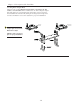
Chapter 3: Mounting the Load Disc Stainless Steel Junction Box Mounting and Wiring Mounting Junction Box Figure 3-7: Plastic and Stainless Steel Junction Box Mounting 1. See Figure 3-7. Hold the junction box at the desired mounting location. Mark the four mounting holes. 2. Mount the junction box with #8-32 socket head cap screws and flat washers per your application. Tighten the screws until snug. Wiring Load Discs to Junction Box See Figure 3-8.
Chapter 3: Mounting the Load Disc Note: Ground the cable shield only at the signal processor. 2. Thread the Load Disc cable through the desired conduit fitting. (See Figure 3-8). 3. Estimate the required length of cable to the terminal strip, allowing a little extra for strain relief. Cut the excess cable. 4. Strip back 3” (76mm) of the cable sheathing to expose the three wires inside. Strip back 1/4” (6mm) of insulation from the end of each of the wires. 5.
Chapter 3: Mounting the Load Disc CAUTION: Only use Sikaflex™ 1A polyurethane sealant or Dow Corning™ RTV 739 or RTV 738. Other sealants may contain acetic acid, which is harmful to sensors and electronics. 4. Route another 3-conductor cable through the fitting into this junction box, and attach wires to the TB1 TB2 terminal: black wire to B, white wire to W, and brown or red wire to R. 5. Repeat Steps 3 and 4 until all junction boxes on the vessel are wired together. 6.
Appendix A: Contact Information Appendix A: Contact Information Contact Information Technical Service You may reach Kistler-Morse headquarters at the following: Mail: Kistler-Morse 150 Venture Boulevard Spartanburg, SC 29306 USA Telephone: 1-800-426-9010 (864) 574-2763 Fax: (864) 574-8063 E-mail: sales@kistlermorse.com Website: http://www.kistlermorse.com A complete, unabridged copy of our product warranty is available upon request from KM.
Appendix A: Contact Information On-Site Consultation KM’s Field Service staff can provide additional services at your request. Contact KM for rate and scheduling information for the following services: Note: Load Disc installation, field wiring, conduit installation, and junction box and signal processor mounting must be performed by the customer. The AC power must be connected to the signal processor, but not energized, prior to KM beginning work.
Appendix B: System Calibration for the Load Disc Appendix B: System Calibration for the Load Disc This chapter describes general procedures for calibrating the Load Disc system. Calibration Methods Before calibrating, install a signal processor. Refer to the signal processor manual for the procedures to input calibration parameters. There are two calibration methods: • Live Load calibration — set lo span and hi span while moving material into or out of the vessel. This is the preferred method.
Appendix C: Troubleshooting the Load Disc System Appendix C: Troubleshooting the Load Disc System This section describes an output check and some common problems. For each problem, one or more possible explanations are listed. For each explanation, suggested solutions are provided. Functional Check: Measuring Output Note: The “no-load” condition is when the Load Disc stands alone without any weight applied. SENSOR TEST OFF METER ON SIMULATE +EX Red ADJUST 1.
Appendix C: Troubleshooting the Load Disc System Problem Problem Details Small Amplitude Changes or Erratic Fluctuations in display readings Fluctuations can be caused by moisture in cable conduit, junction boxes, or PCBs. Solution Check conduit, junction boxes, and PCBs for water contamination. Find water entry source and correct problem. Dry with a hair drier. Remove/replace corroded parts and materials.
Appendix C: Troubleshooting the Load Disc System Problem Problem Details Solution Small Amplitude Changes or Erratic Fluctuations in display readings Fluctuations can be caused by problems with signal processor. Check signal processor excitation voltage and incoming AC voltage for accuracy and stability (refer to signal processor manual).
Appendix D: Technical Drawings Appendix D. Technical Drawings (TI) This appendix contains the following technical drawings for the Load Disc: Drawing No. Drawing Titile TI-LC.
OPTION 1 J BOX ELECTRONICS OPTION 2 ELECTRONICS LD360s TYPICAL CABLING DIAGRAM OPTION 3 ELECTRONICS
HAZARDOUS LOCATION JUNCTION BOX TYPICAL JUNCTION BOX WIRING TYPICAL FOUR CHANNEL INSTALLATION NON-HAZARDOUS LOCATION MODEL SBMVS-N4 INTRINSIC SAFETY BARRIER ASSEMBLY (4 CHANNELS MAX.) TI-LD360s.
HAZARDOUS LOCATION TYPICAL MULTI CHANNEL INSTALLATION NON-HAZARDOUS LOCATION MODEL SBMVS-N4 INTRINSIC SAFETY BARRIER ASSEMBLY (8 CHANNELS MAX.) TYPICAL JUNCTION BOX WIRING B TI-LD360s.
STX TYPICAL CONNECTION FOR STAND-ALONE STX SYSTEMS. MVS TYPICAL CONNECTION FOR TRANSDUCERS (SENSORS) TYPICAL STAHL BARRIER CONNECTIONS TO MVS FOR DIFFERENT APPLICATIONS I.S. BARRIERS MVS INTERFACE TYPICAL CONNECTION FOR STX SYSTEMS, MVS RESIDENT. I.S. BARRIERS (CHAN. 1) I.S. BARRIERS B TI-LD360s.
1Klb-7.
1Klb-25Klb LOAD DISC LD3 TRANSDUCER WITH UNIVERSAL ADAPTER PLATE MOUNTING DIMENSIONS
1Klb-7.
vESSEL MOUNTING HOLE PATTERNS FOR ANYADAPTER TOP ADAPTER PLATE (MINIMUM (4) 1/2” HEX HEAD BLOTS REQUIRED)
1Klb-25Klb LOAD DISC LD3 TRANSDUCER WITH LEVELING BASE ADAPTER PLATE MOUNTING DIMENSIONS
1Klb-25Klb LOAD DISC LD3 TRANSDUCER WITH LEVELING BASE ADAPTER PLATE