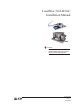
Load Disc 3xi/LD3xiC Installation Manual CAUTION It is essential that all instructions in this manual be followed precisely to ensure proper operation of the equipment.
NOTICE The content of this document is the intellectual property of Kistler-Morse Corporation. Any reproduction or translation of this document without the written authorization of a Kistler-Morse corporate officer is prohibited. CAUTION Follow these rules if welding is done on the vessel after installation of the Load Disc. The electrical current of the welder may pass through the Load Disc, causing damage to the transducer and possibly to the signal processor.
Table of Contents Table of Contents Introduction....................................................................................................i Welcome ........................................................................................................................................................... i About this manual ............................................................................................................................................ i Manual Conventions ...............
Table of Contents PB
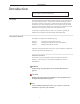
Introduction Introduction This chapter describes the organization, manual conventions, and provides specification information . Welcome This manual describes the installation of the Load Disc 3xi/3xiC load cell and its various hardware options. It includes procedures for leveling and shimming of the vessel if it is neccessary. Instructions for wiring the load cell to the junction boxes and wiring the junction boxes together and to the signal processor are also included.
Introduction Specifications LD3xi LD3xiC/LD3xiMJ Mechanical Mechanical Compression: 3 x rated load Compression: 3 x rated load Tension: 1 x rated load Tension: 1 x rated load Shear (capacity 220 lbs -2200 lbs): 0.5 x rated load Shear: 0.5 x rated load Functional Integrity: 1.5x rated load (compression) (capacity 5500 lbs): 0.25 x rated load Functional Integrity: 1.
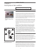
Chapter 1. Description Chapter 1: Description of the Load Disc This chapter describes the Load Disc 3xi/3xiC/3xiMJ Compression Load Cell and its installation options.
Chapter 1. Description Installation Option Descriptions This section will briefly describe the following hardware options: Universal Top Plate Adapter, Leveling Top Plate Adapter, Anyadapter Plate and Leveling Base Adapter Plate. As well as the LD3xiC Load Cell configuration. See Chapter 2 and 3 for more specific installation instructions and refer to the TI drawings located in Appendix D.
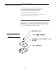
Chapter 1. Description Leveling Top Plate Adapter This option consists of the Universal Top Adapter Plate, a hex head bolt, spherical washer set and jam nuts. The adapter plate attaches to the load disc with the hex bolt and hardware. The adapter plate then bolts to a vessel gusset or a flat plate welded to the vessel leg, using customer-supplied hardware. This hardware arrangement allows 360 degree movement of the top plate and angular misalignment of up to 3 degrees.
Chapter 1. Description Leveling Base Adapter Plate This kit consists of a Leveling Base Adapter Plate and four hex bolts, four flat washers, and four lock washers. The LD360S bolts onto the leveling base adapter plate. This plate rests on four leveling nuts and washers screwed onto anchor bolts installed in the foundation. By turning the leveling nuts, the height of the load discs and thus the vessel, can be adjusted for proper load distribution. Note: Adapter plate not shown in illustrationat right.
Chapter 2. Pre-Installation Chapter 2: Preparing for the Load Disc Installation This chapter describes the pre-check procedures for the LD3xi/LD3xiC. Checking the load discs before installation will ensure properly working equipment that will provide accurate monitoring of vessel contents.
Chapter 2. Pre-Installation Measuring Sensor Output To measure the output of the LD3xi/LD3xiC, the sensor needs to have an excitation voltage applied to it from a signal processor, a DC voltage generator, or a KM test meter. To use the excitation from the KM Test Meter, put the switch in the simulate position and wire the positive to the red position and the negative to the black position.
Chapter 2.
Chapter 2. Pre-Installation Factors that affect Performance An independent, isolated vessel with no connection to any other vessel or adjacent structure provides the most accurate results for a weight measurement system. Examples of this type of application are floor scales and truck scales. Connections to other vessels or structures affect accuracy because the transducers interpret strain changes caused by the connecting structures as being caused by changes in the material weight.
Chapter 3. LD3xi/LD3xiC Mounting Chapter 3: Mounting the Load Disc This chapter describes installation and wiring of the LD3xi/LD3xiC and junction boxes. Follow all instructions carefully to ensure proper operation of the system. General Information The load disc has a variety of mounting hardware options that accommodate almost all possible applications.
Chapter 3. LD3xi/LD3xiC Mounting LD3xi/LD3xiC General Installation This section describes the installation procedures for the following hardware options: Universal Top Plate Adapter, Leveling Top Plate Adapter, Anyadapter Plate, Leveling Base Adapter Plate as well as the LD3xiC. 1. Prior to installing the load cell, verify that they are the correct capacity for your application by reviewing the information on the label. 2. Measure the load cell voltage output. With no-load, the meter should read 0mV.
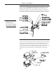
Chapter 3. LD3xi/LD3xiC Mounting 5. Raise the vessel. 6. Inspect the foundation and vessel mounting surfaces that will mate to the LD3xi/LD3xiC plates. a. Check the mounting hole locations and size on both the foundation base and the vessel foot pad. (Refer to the TI drawings, Appendix D.) b. Also check the surfaces for flatness and angular misalignment. A baseplate with leveling nuts is recommended. (See Figure 3-1) 7. Mount the LD3xi/LD3xiC assembly to the foundation.
Chapter 3. LD3xi/LD3xiC Mounting 9. Mount the vessel to the LD3xi/LD3xiC. a. Lower the vessel gently onto the Load Discs. (Alignment pins may be used to help guide and position the vessel.) (See Figure 3-4) b. Center the Load Disc top mounting holes with the vessel mounting holes, using the clearance available from the bottom mounting holes. Note: If the vessel hole pattern does NOT match up with the Load Disc hole pattern, modify the mounting holes on the vessel.
Chapter 3. LD3xi/LD3xiC Mounting Leveling and Shimming Note: For installations where leveling nuts are not used, load balancing on the Load Discs must be achieved by adding or removing shims. Adjusting the Load Discs to distribute the vessel weight evenly may require adding shims (supplied by customer) systematically to all disc locations. Note: The Universal Top Plate will accomodate angular misalignment up to three degrees maximum.
Chapter 3. LD3xi/LD3xiC Mounting Note: Shimming the plates of one Load Disc will probably affect the weight distribution on the Load Disc located on the opposite side. Keep this in mind while shimming. CAUTION: If you need to raise the vessel or one vessel leg after installation, loosen the bolts on all Load Discs to prevent overloading. Leveling/Shimming for the Leveling Top plate Adapter, Leveling Base Adapter Plate, and the Anyadapter Plate 1.
Chapter 3. LD3xi/LD3xiC Mounting Junction Box Mounting and Wiring Mounting Junction Box Figure 3-6: Plastic and Stainless Steel Junction Box Mounting CAUTION: Only use Sikaflex™ 1A polyurethane sealant or Dow Corning™ RTV 739 or RTV 738. Other sealants may contain acetic acid, which is harmful to sensors and electronics. Note: If you have a 61-6036-01 Stainless Steel J-Box with trimming pots, refer to page 3-10. 1. See Figure 3-6. Hold the junction box at the desired mounting location.
Chapter 3. LD3xi/LD3xiC Mounting 7. Perform Steps 3 through 6 for each Load Disc you wire to this junction box. 8. Replace the junction box cover if not ready to begin wiring the junction boxes together. Wiring Junction Boxes Together and to Signal Processor Notes: 1. 2. 3. 4. 5. The procedure below assumes the conduit fitting and conduit for wiring the junction box to the other junction boxes and to the signal processor has been installed. Seal all conduit fittings against water entry.
Chapter 3. LD3xi/LD3xiC Mounting CAUTION: Only use Sikaflex™ 1A polyurethane sealant or Dow Corning™ RTV 739 or RTV 738. Other sealants may contain acetic acid, which is harmful to sensors and electronics. 6. Route the cable from the last junction box through conduit to the signal processor. Refer to the signal processor manual for wiring the junction box to the signal processor.
Chapter 3. LD3xi/LD3xiC Mounting Trim Box Mounting and Wiring Mounting Trim Box 1. See Figure 3-9. Hold the junction box at the desired mounting location. Mark the four mounting holes. 2. Mount the junction box with #8-32 socket head cap screws and flat washers. Tighten the screws until snug. Wiring Load Discs to Trim Box See Figure 3-10. The summing stainless steel junction box accommodates up to eight Load Discs. Follow this procedure: Figure 3-9: Summing Stainless Steel Junction Box Mounting 1.
Chapter 3. LD3xi/LD3xiC Mounting 8. A calibration of the electronic indicator is needed before before trimming functions can be done. Refer to the electronic indicator manual for the calibration procedure. 9. Place test weights above each load cell and record the weight value displayed on the electronic indicator. The test weights should be directly above each load cell and not overhanging. 10. The cell that has the lowest weight displayed will not be adjusted; it will be the reference load cell.
Chapter 3.
Appendix A. Contact Information Appendix A: Contact Information Contact Information You may reach Kistler-Morse corporate headquarters at the following: Mail: Kistler-Morse 19021 120th Ave NE Suite 101 Bothell, Washington USA 98011-9513 Telephone: 1-800-426-9010 (425) 486-6600 Fax: (425) 402-1500 E-mail: sales@kistlermorse.com Website: http://www.kistlermorse.com European Office Technical Service Mail: Kistler-Morse Rucaplein 531 B-2610 Wilrijk-Belgium Telephone: Fax: 32.3.218.99.99 32.3.
Appendix A. Contact Information On-Site Consultation KM’s Field Service staff can provide additional services at your request. Contact KM at the closest office for rate and scheduling information for the following services: Note: Load Disc installation, field wiring, conduit installation, and junction box and signal processor mounting must be performed by the customer. The AC power must be connected to the signal processor, but not energized, prior to KM beginning work.
Appendix B. System Calibration Appendix B: System Calibration for the Load Disc This chapter describes general procedures for calibrating the Load Disc system. Calibration Methods Before calibrating, install a signal processor. Refer to the signal processor manual for the procedures to input calibration parameters. There are two calibration methods: • • Live Load calibration — set lo span and hi span while moving material into or out of the vessel. This is the preferred method.
Appendix B.
Appendix C. Troubleshooting Appendix C: Troubleshooting the Load Disc System This section describes an output check and some common problems. For each problem, one or more possible explanations are listed. For each explanation, suggested solutions are provided. Functional Check: Measuring Output (while wired to Signal Processor) Note: The “no-load” condition is when the Load Disc stands alone without any weight applied. 1. Mesure the output of the load cell using procedure from page 2-2. 2.
Appendix C. Troubleshooting Problem Problem Details Small Amplitude Changes or Erratic Fluctuations in display readings Fluctuations can be caused by moisture in cable conduit, junction boxes, or PCBs. Solution Check conduit, junction boxes, and PCBs for water contamination. Find water entry source and correct problem. Dry with a hair drier. Remove/replace corroded parts and materials.
Appendix C. Troubleshooting Problem Problem Details Solution Small Amplitude Changes or Erratic Fluctuations in display readings Fluctuations can be caused by problems with signal processor. Check signal processor excitation voltage and incoming AC voltage for accuracy and stability (refer to signal processor manual).
Appendix C.
Appendix D. Technical Drawings Appendix D. Technical Drawings (TI) This appendix contains the following technical drawings for the LD3xi: Drawing No. TI-LC.
Appendix D.